Part 24 – At Long Last

Again, I need to apologise to everyone for the extremely long delay since the last build diary.  Here at the Archive we’ve been working to finish all of the material for the exhibition which will open in the New Year at the Chadwick Centre on Canwick Hill near Lincoln and that has been taking up the vast majority of our time.


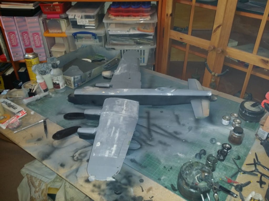
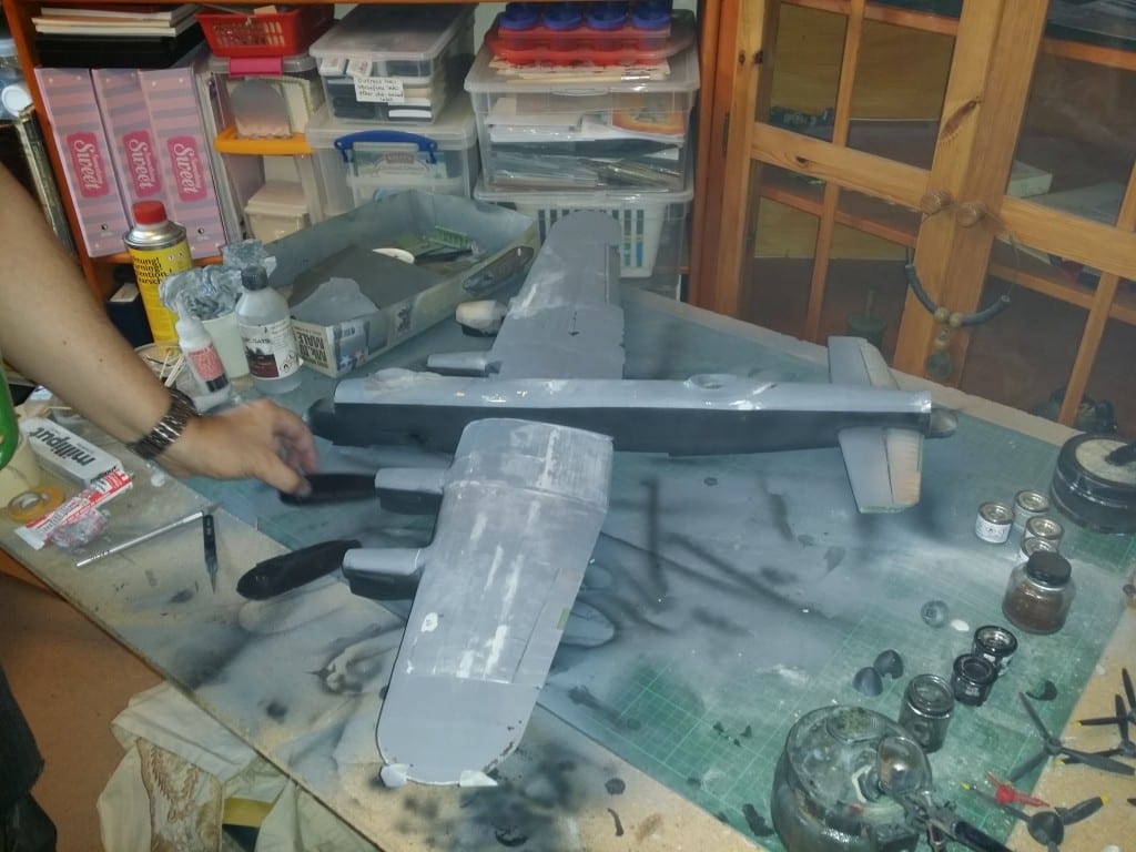
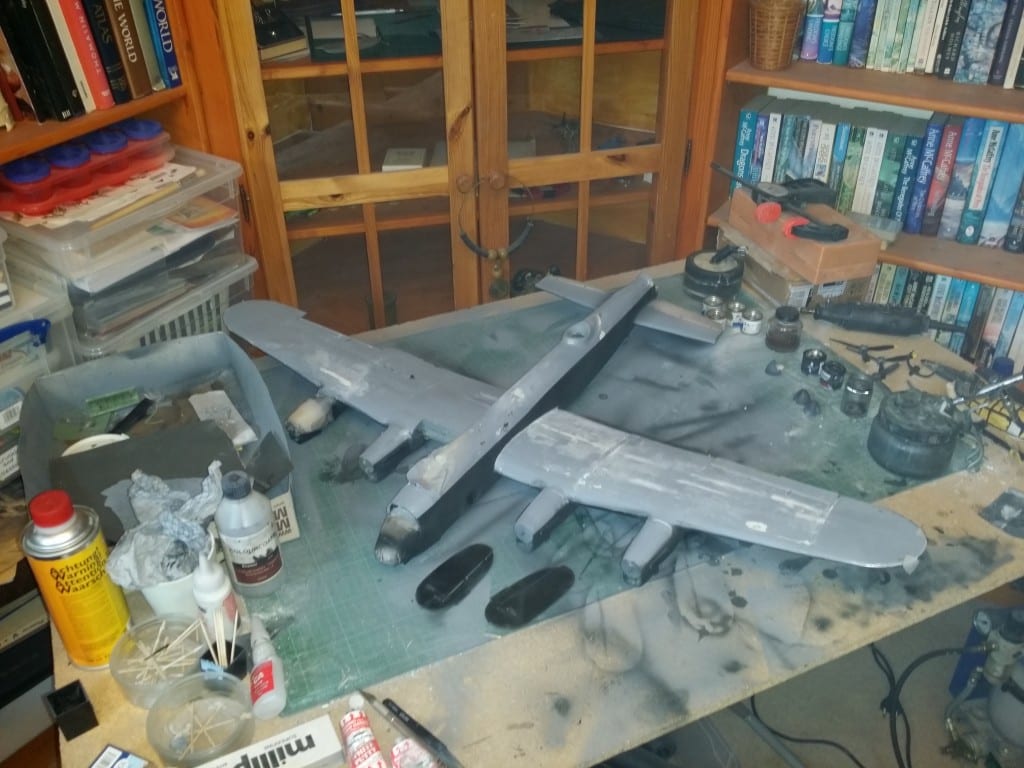
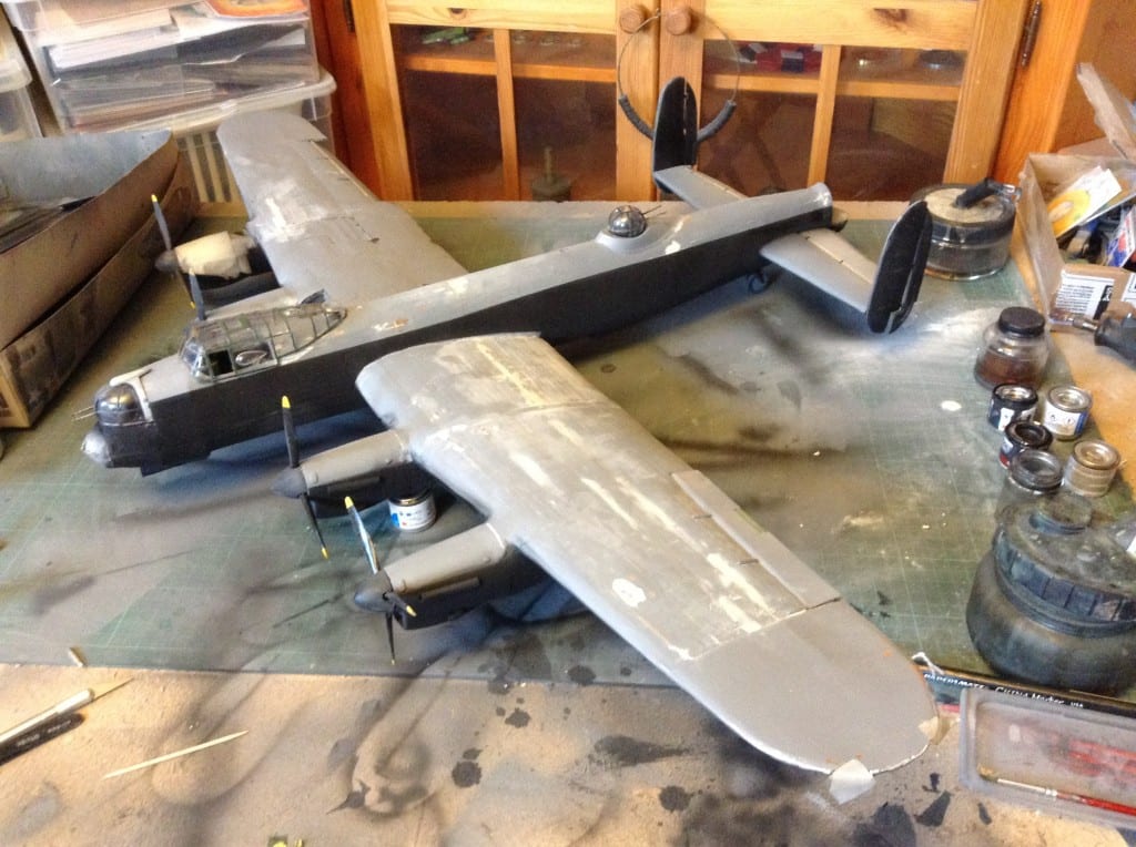
Last time we discussed creating the decals of the nose art selected in the poll, and talked about finishing off the main fuselage prior to painting it. The last blog ended with a photograph of the model with the black paint on its underside.

Pic 23-34

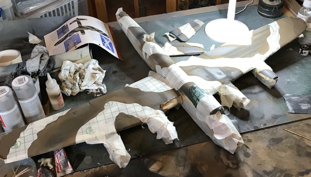
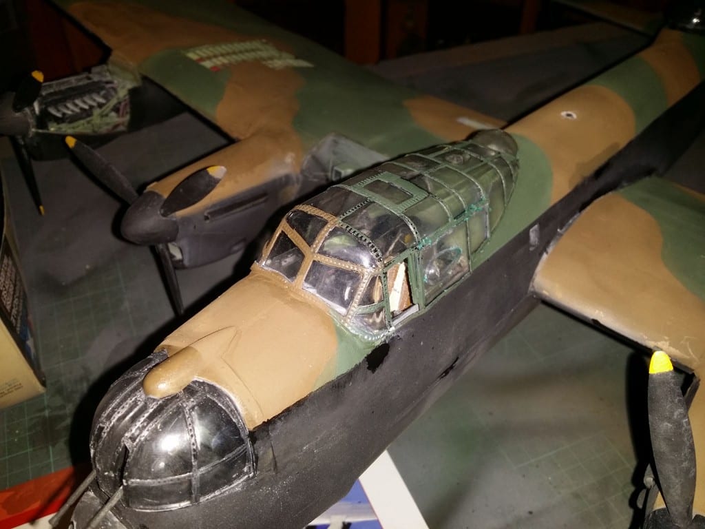
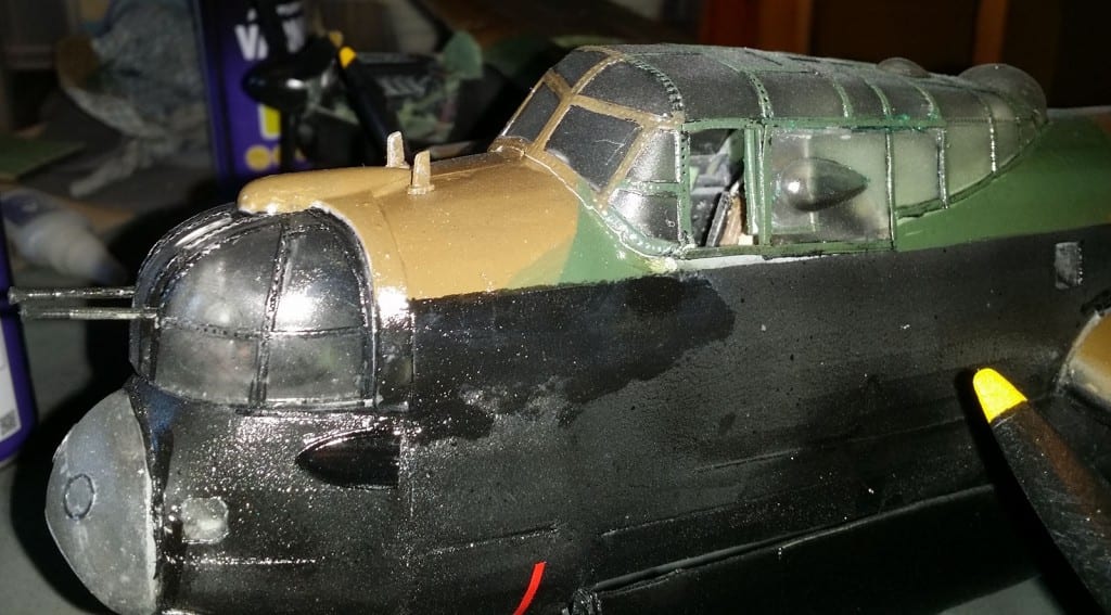
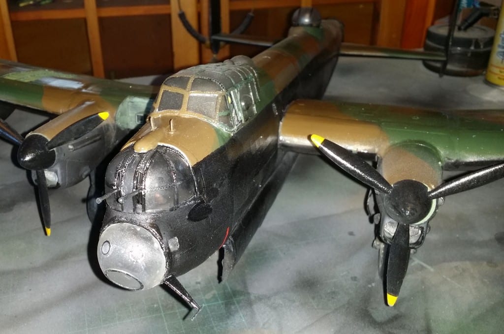
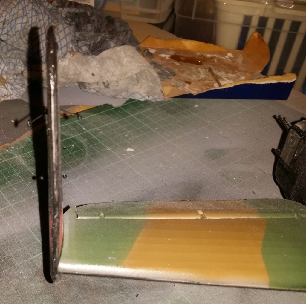
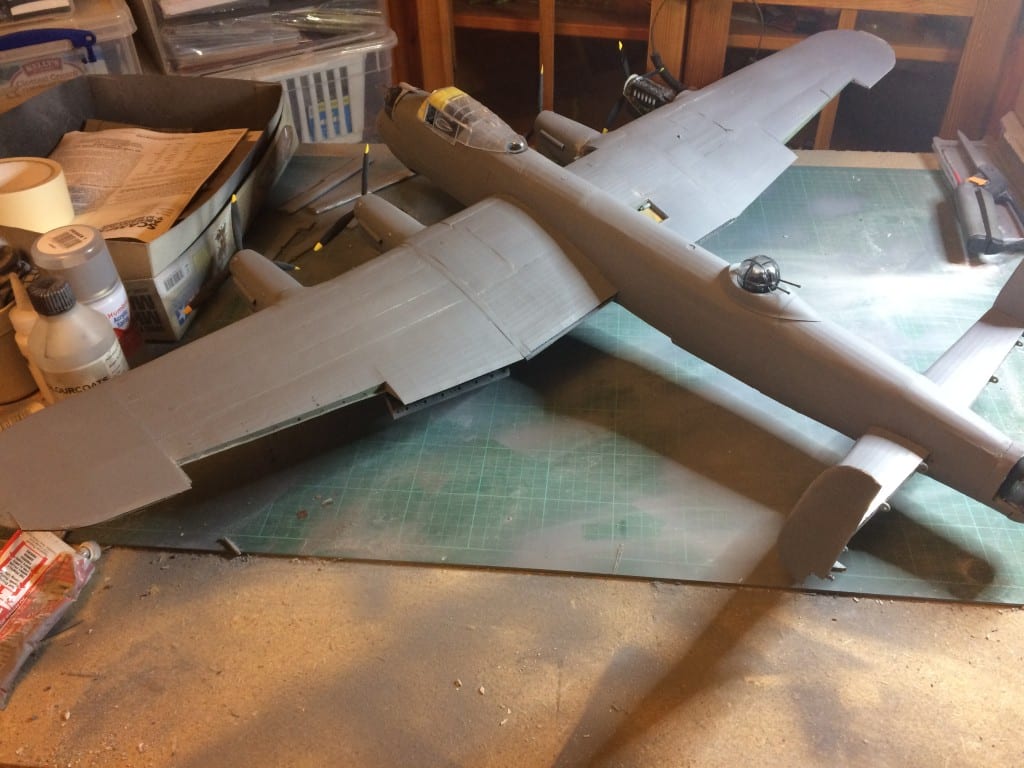
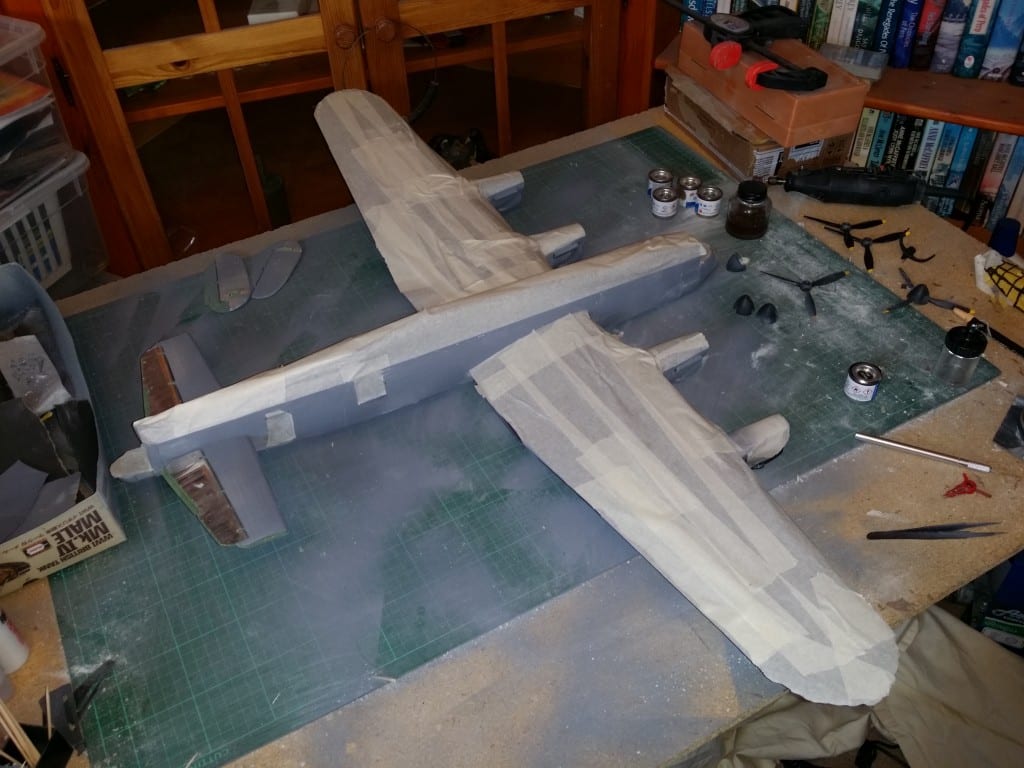
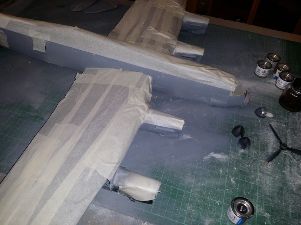
In the last month work on the model has continued apace, starting with a base coat of brown paint to start creating the camouflage, before masking the model to add the green part of the colour scheme.

Pic 24-01

Which was duly added.

Pic 24-02

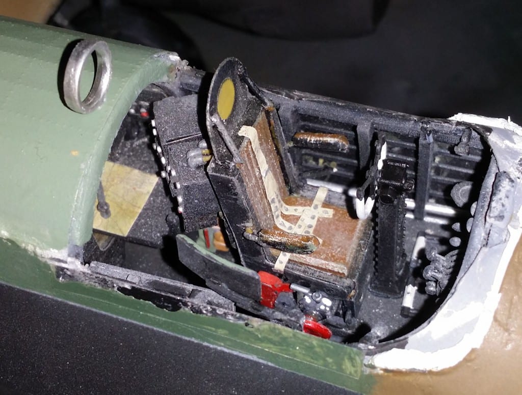
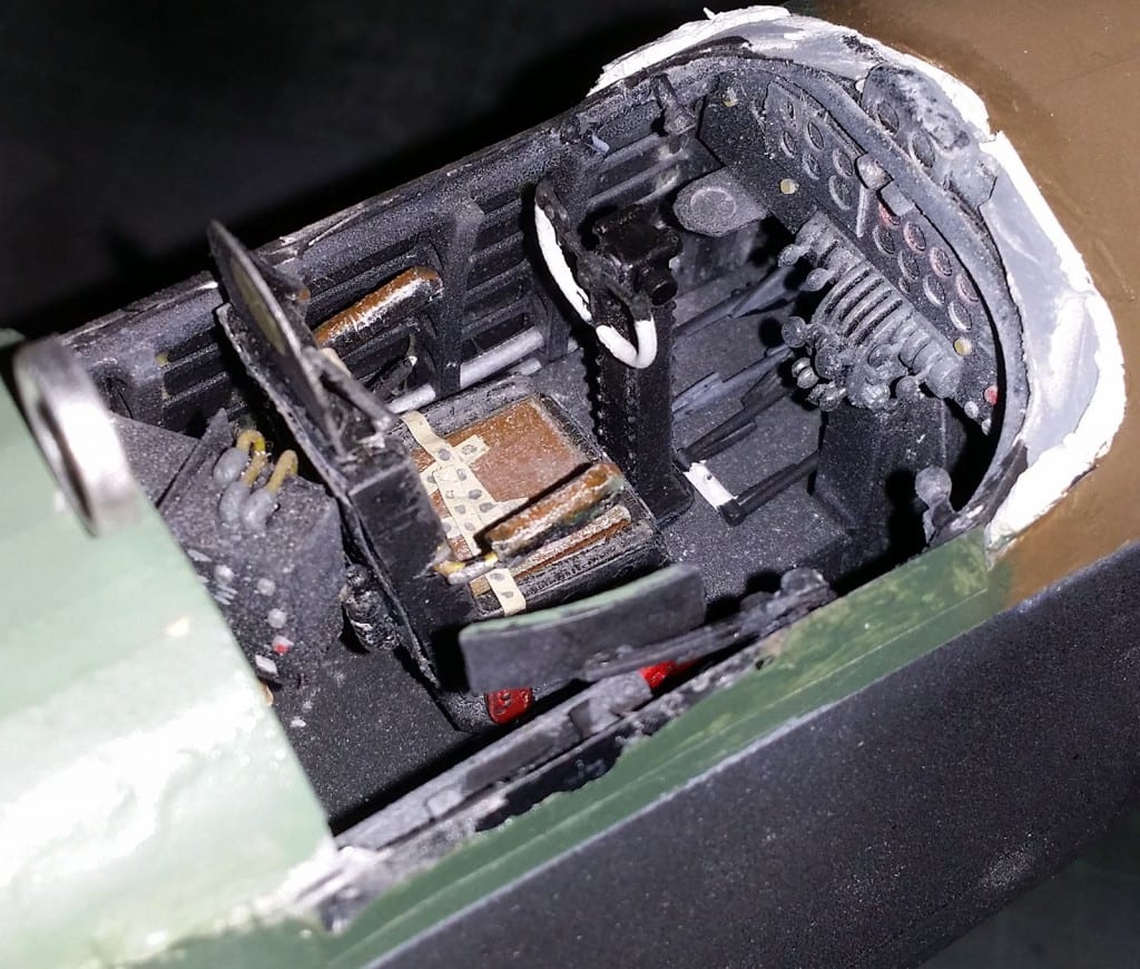
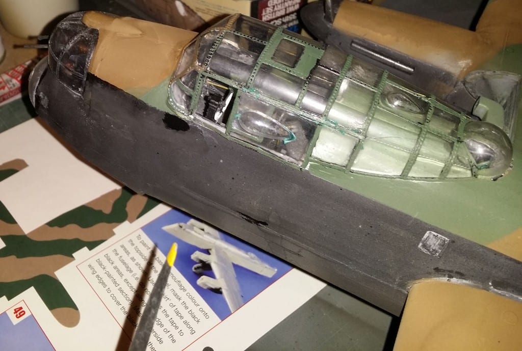
We also finalised the cockpit, adding the pilot’s seat, control column, trim controls and rudder pedals to the cockpit.

Pic 24-03

Pic 24-04

Before attaching the canopy.

Pic 24-05

Pic 24-06

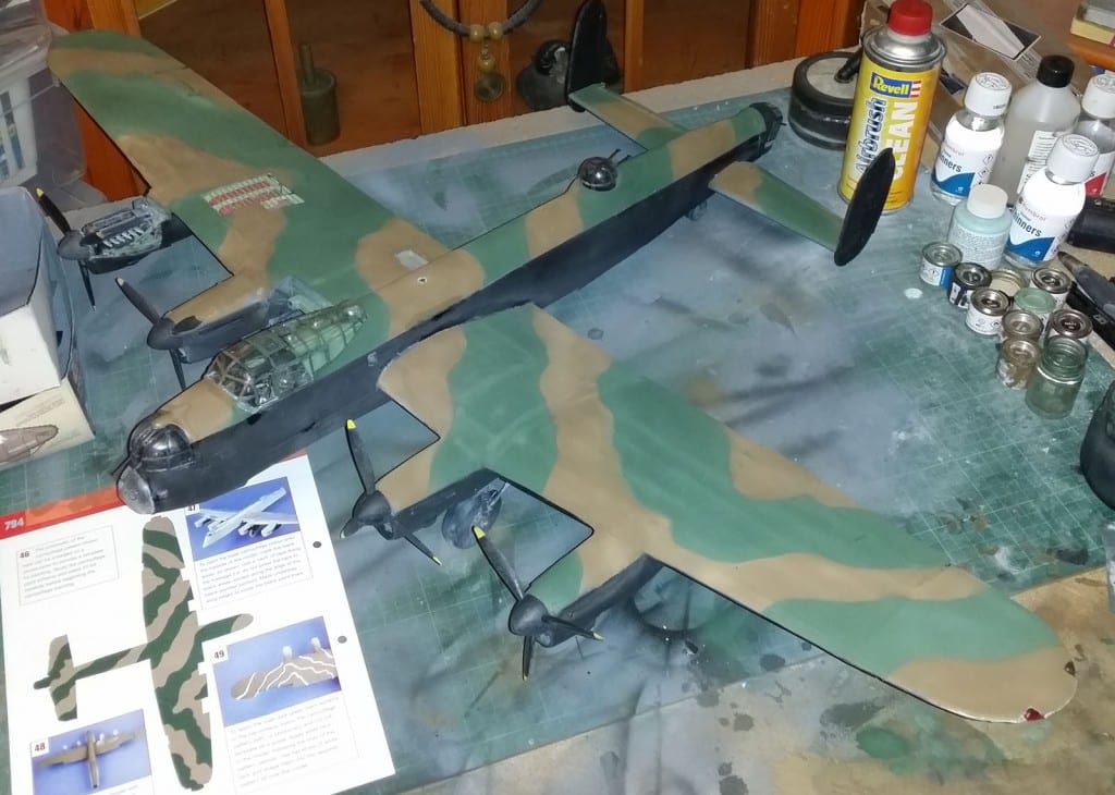
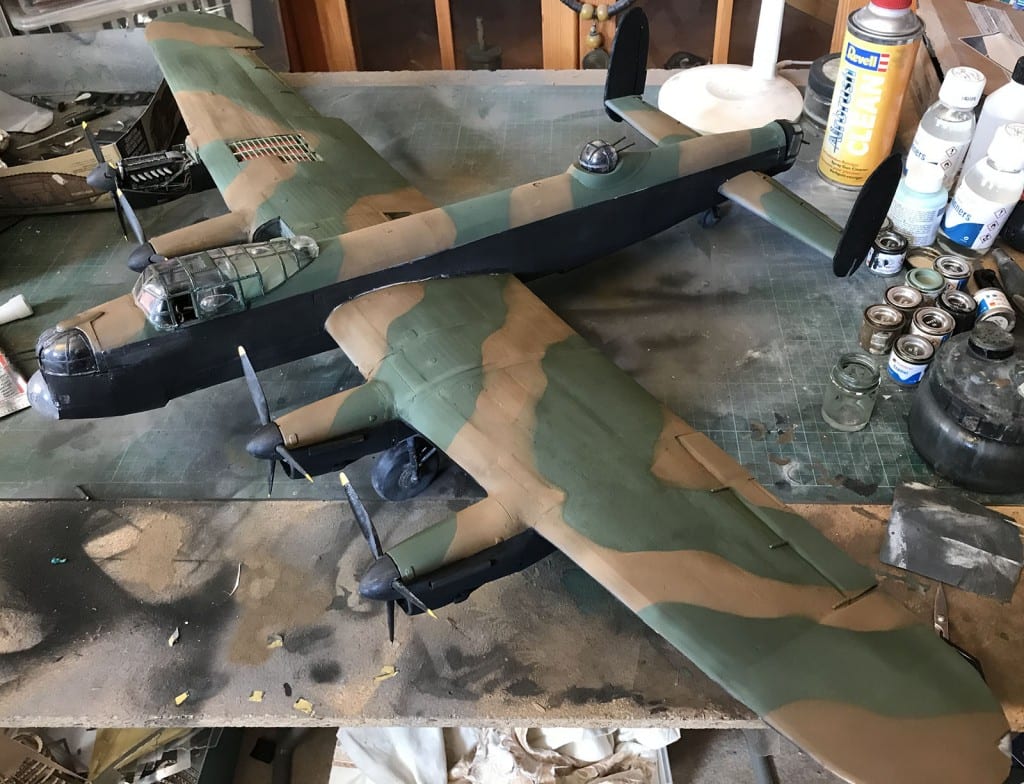
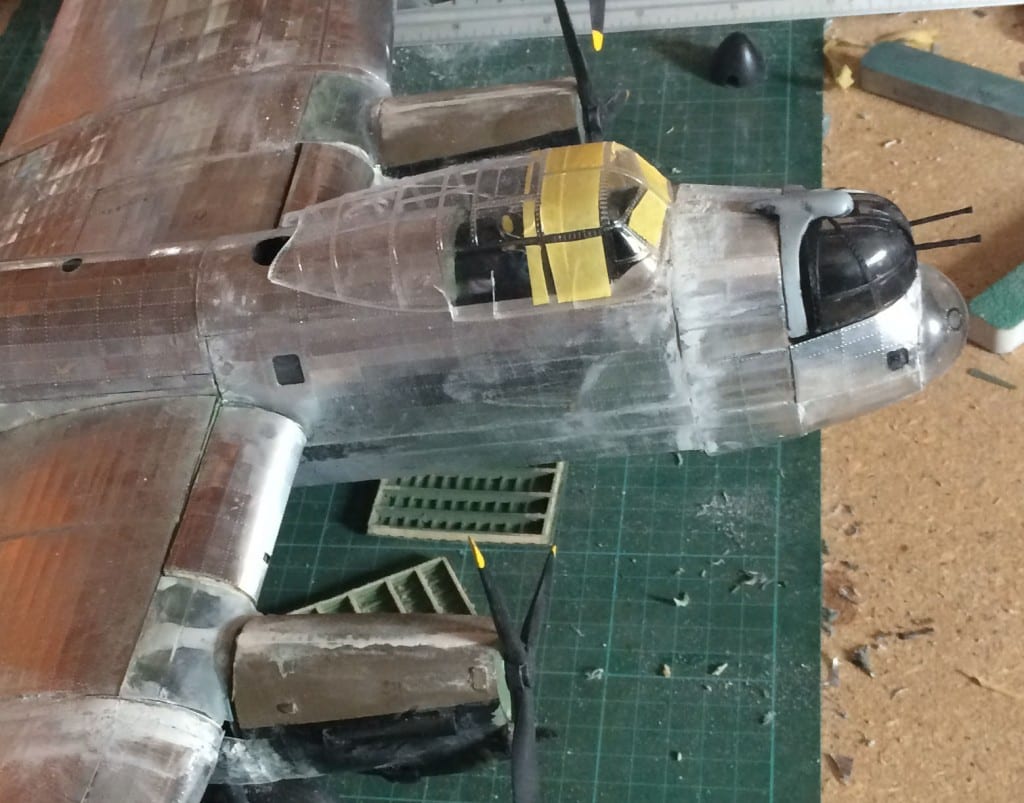
At this stage, the model looked like this.

Pic 24-07

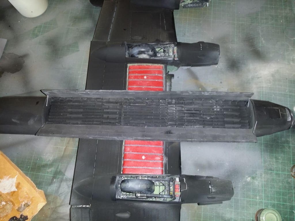
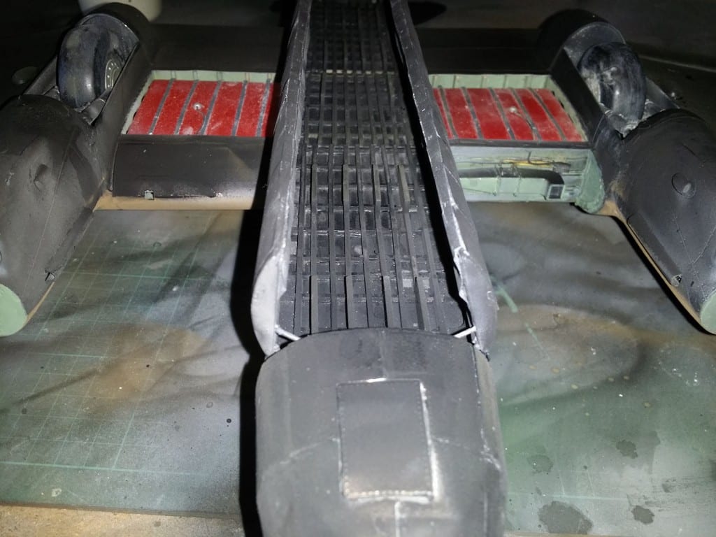
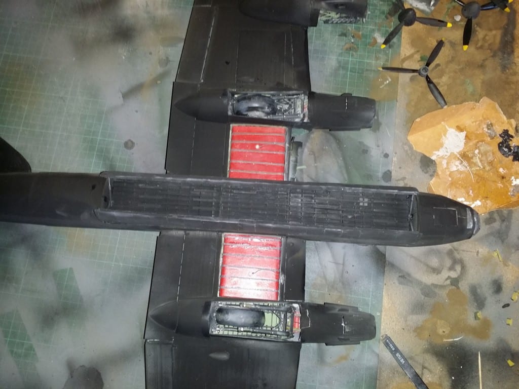
We then moved on to adding the bomb bay doors.

Pic 24-08

Which involved first, attaching the hinges to the model.

Pic 24-09

Before attaching the pins to a mount installed into the bomb bay.

Pic 24-10

Pic 24-11

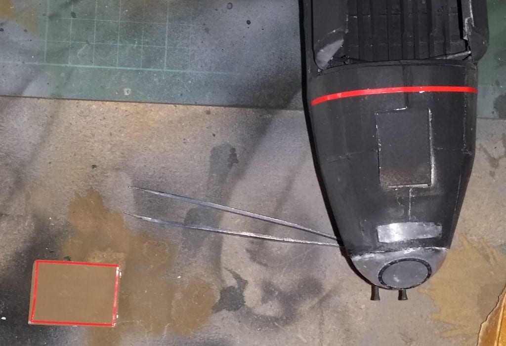
Whilst the model was upside-down we took the opportunity to add the red line along the underside of the nose, and the red rectangle around the dinghy hatch.

Pic 24-12

Pic 24-13

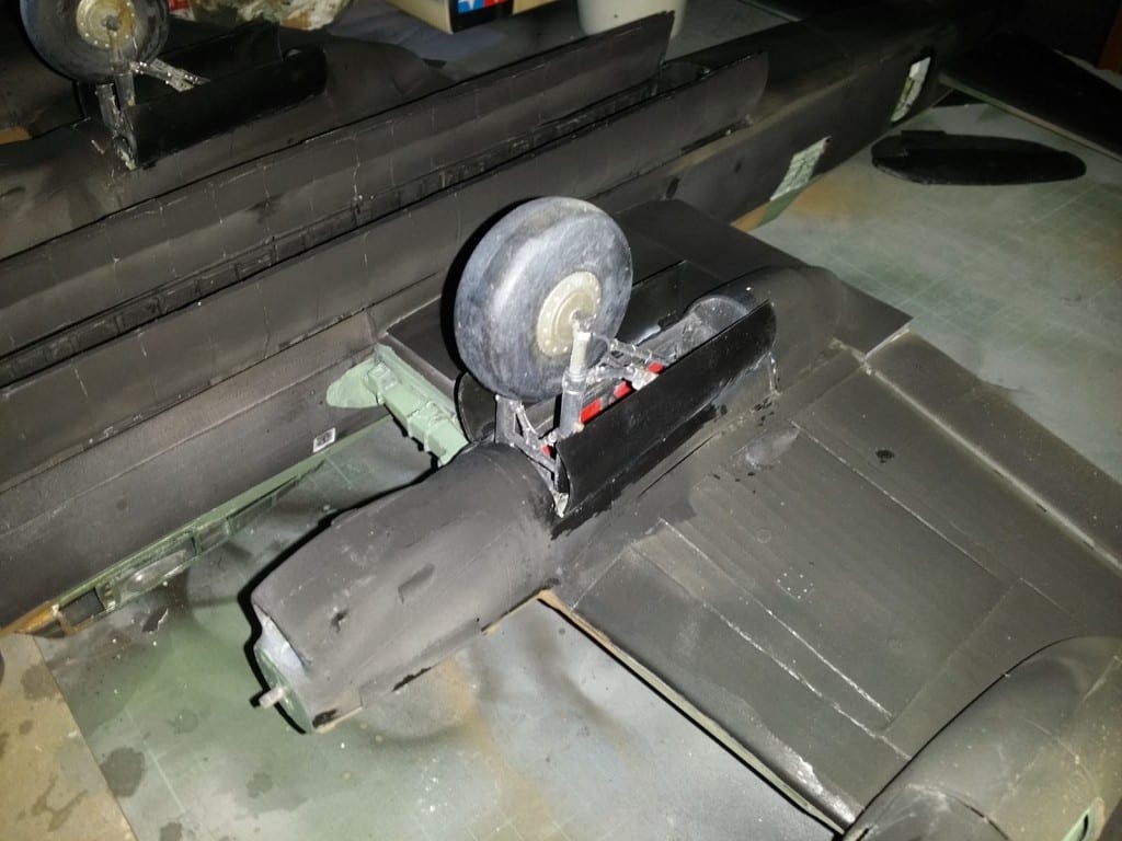
We also took the opportunity to permanently extend the undercarriage, and attach the undercarriage bay covers.

Pic 24-14

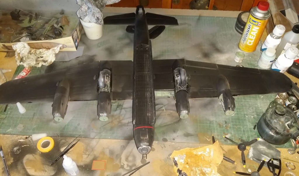
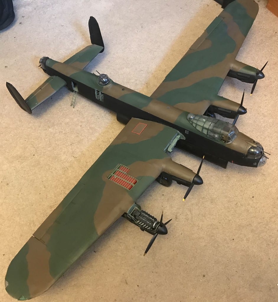
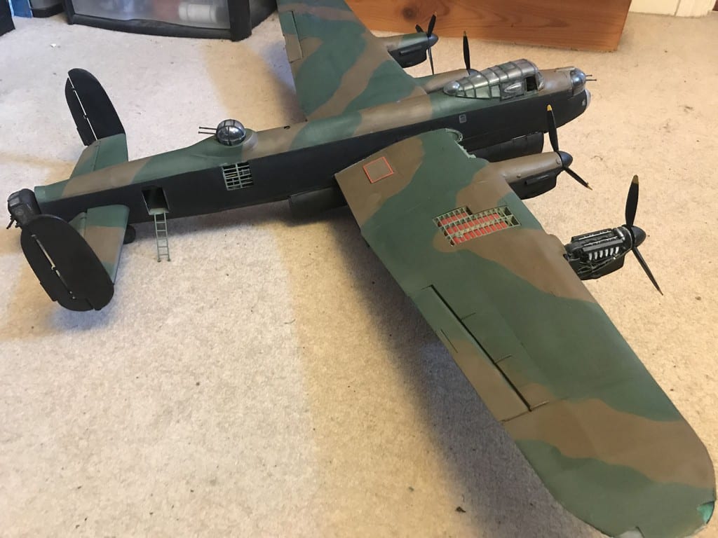
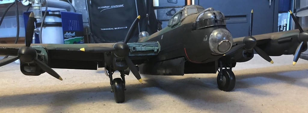
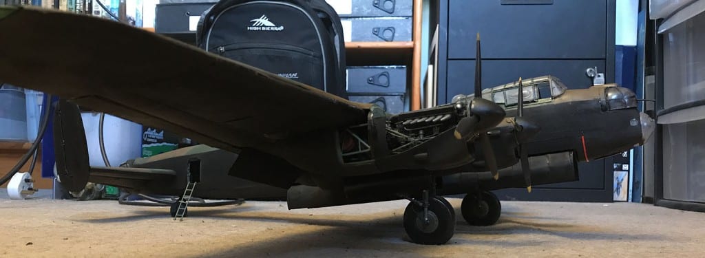
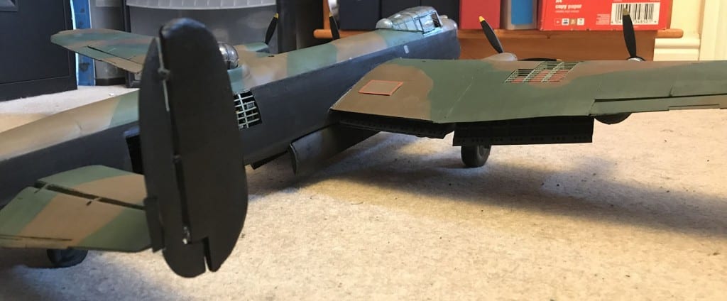
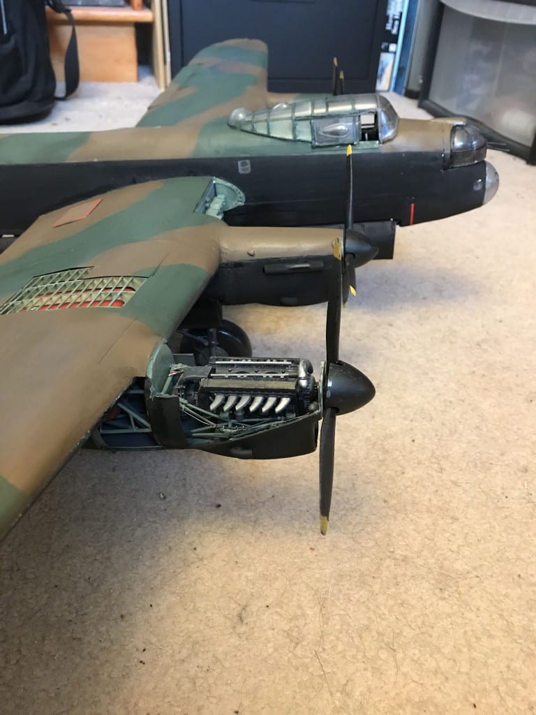
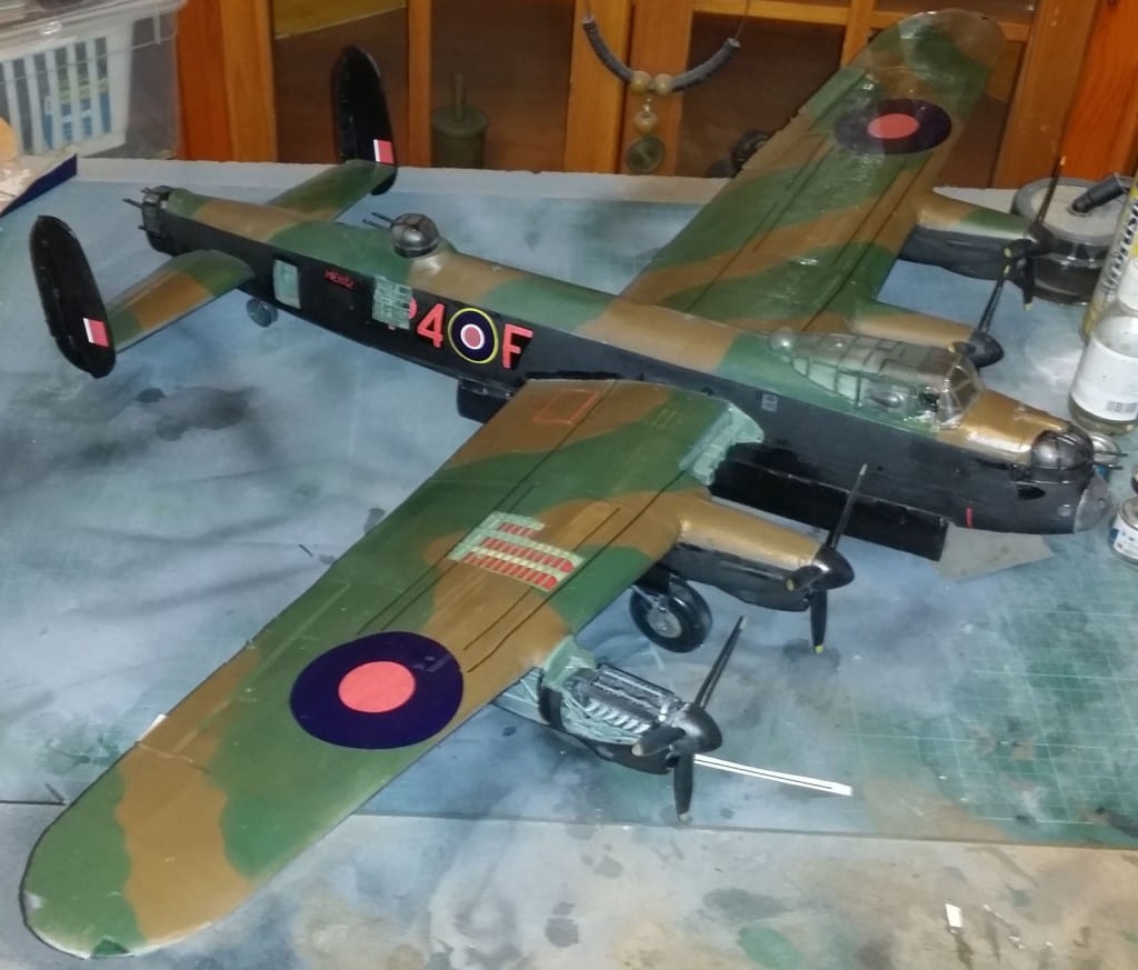
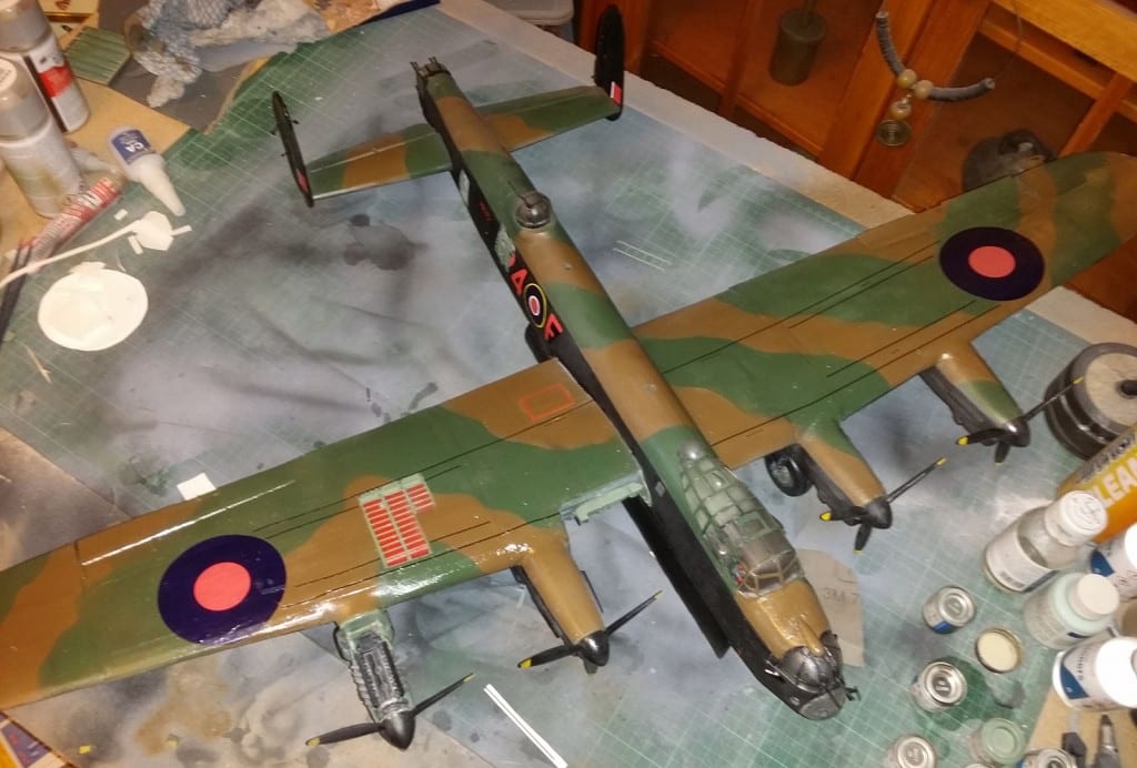
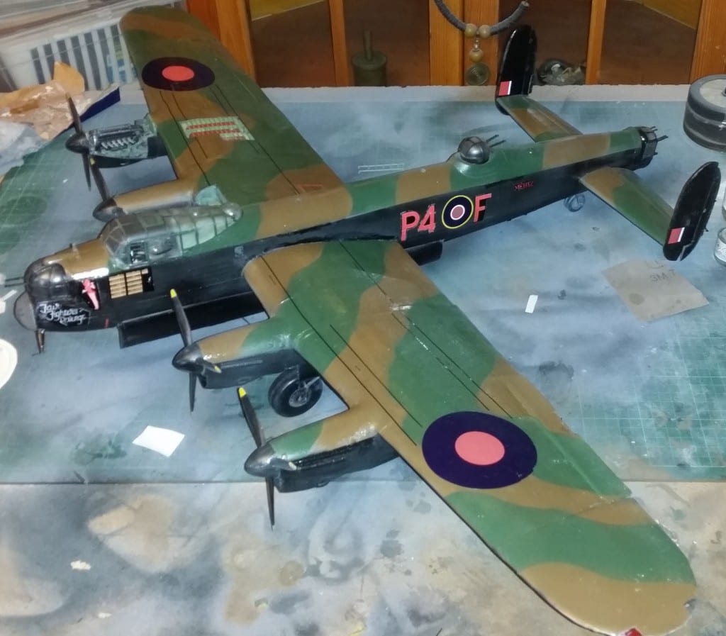
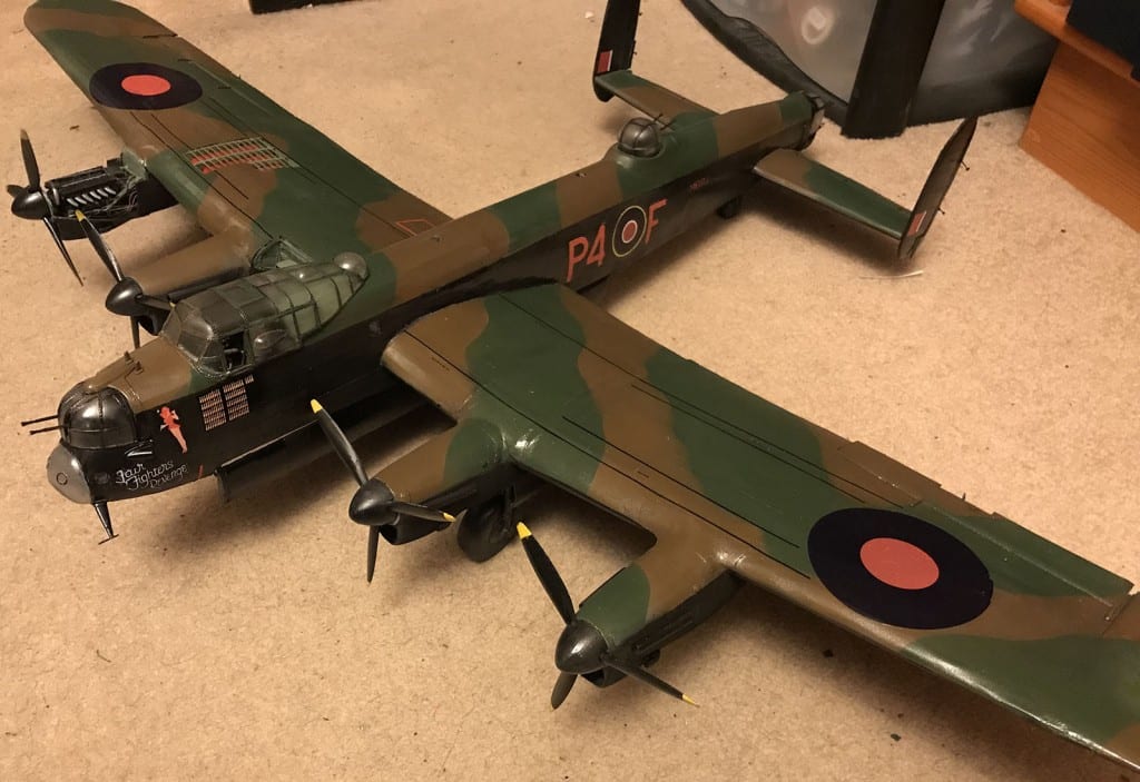
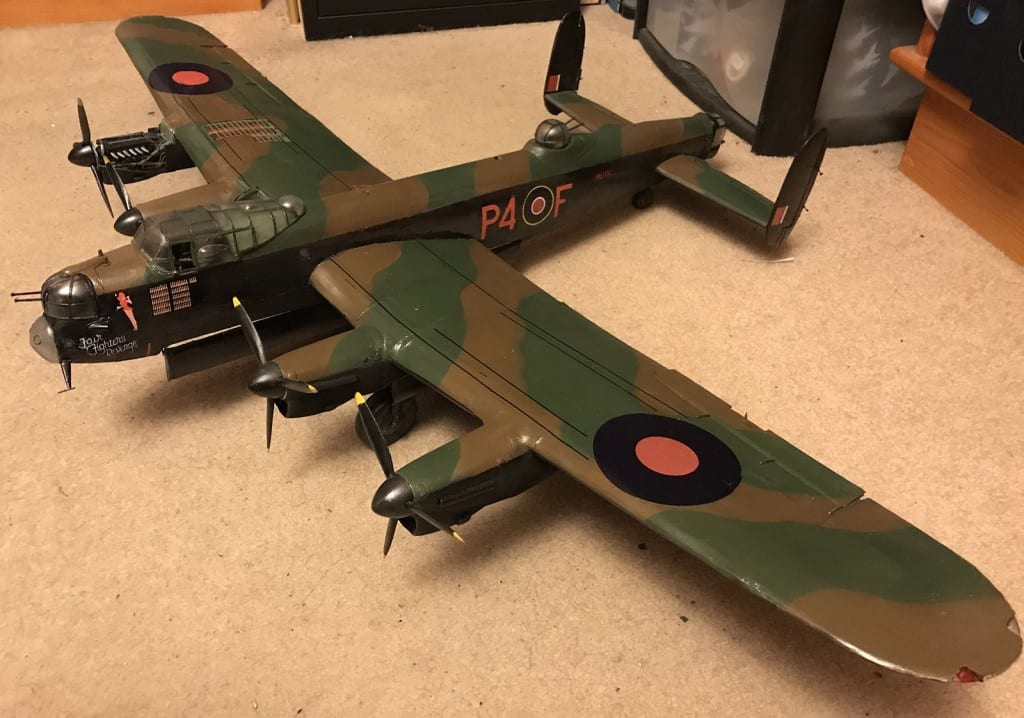
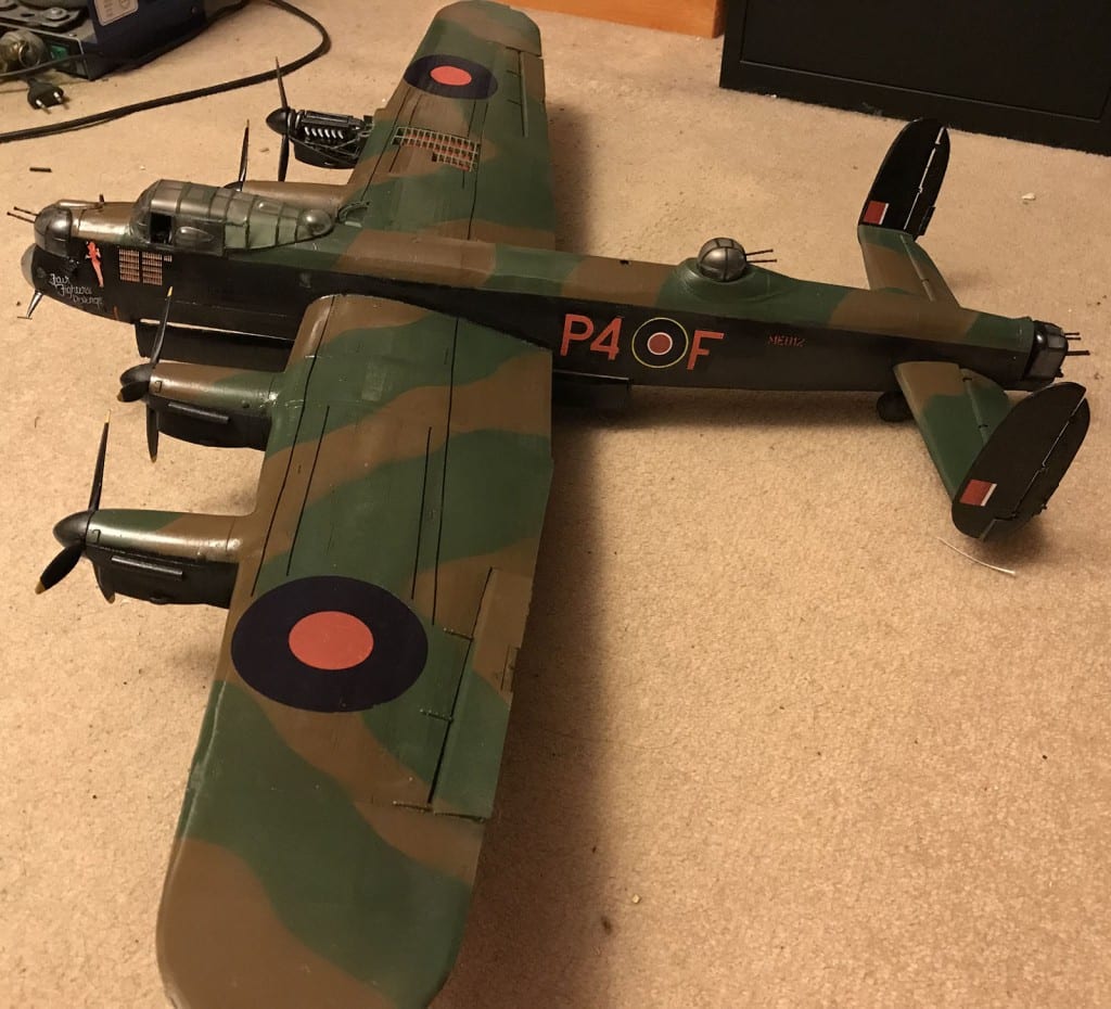
Before righting the model for a final time (and taking a lot of photographs to commemorate the situation).

Pic 24-15 Pic 24-16 Pic 24-17 Pic 24-18 Pic 24-19 Pic 24-20

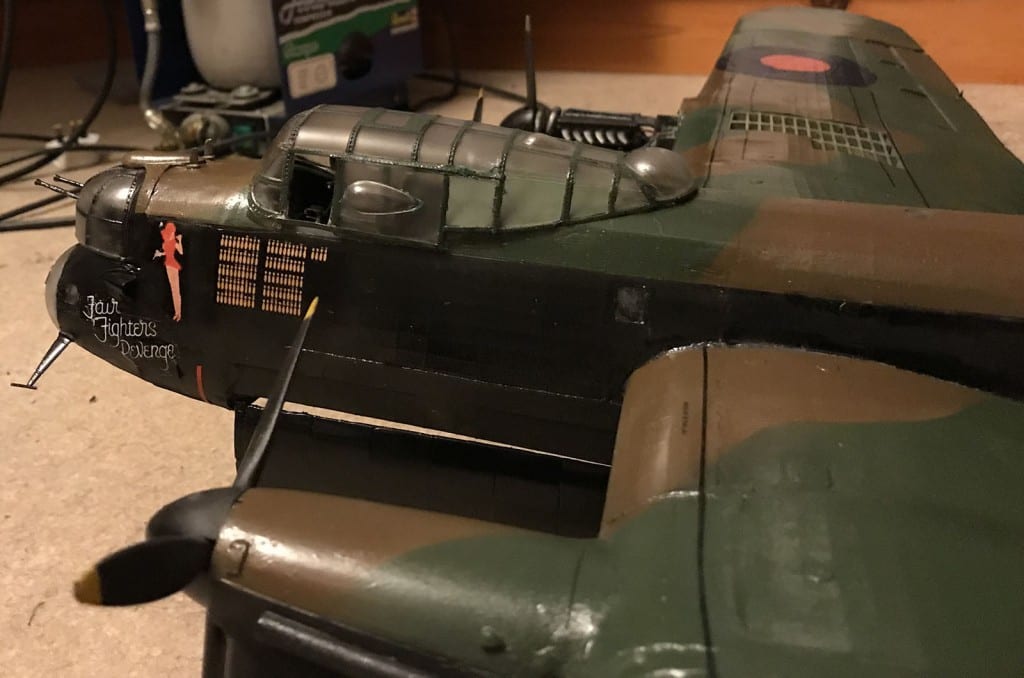
Next, we added most of the remaining small details to the model including the two fins on the nose, a pitot tube and small details on the control surfaces.

Pic 24-21

Pic 24-22

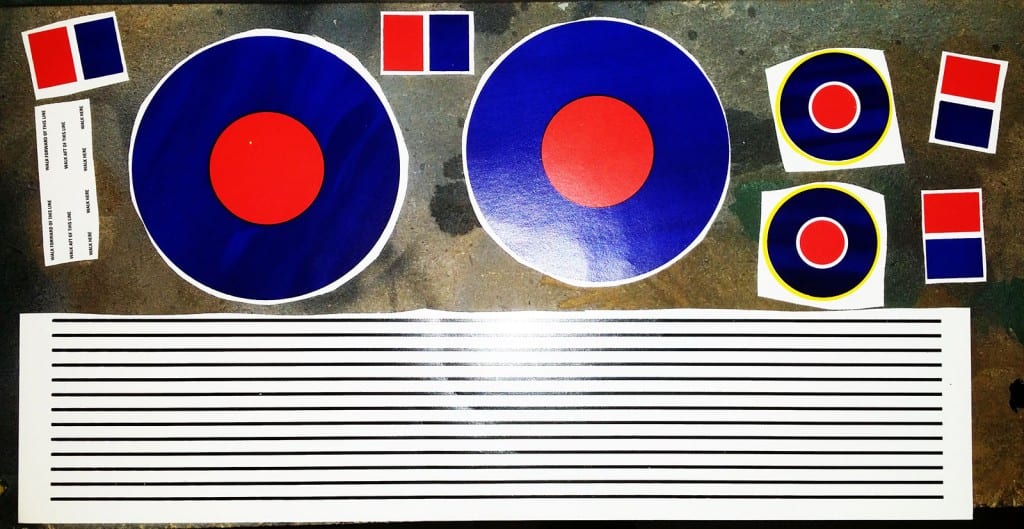
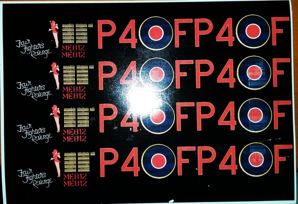
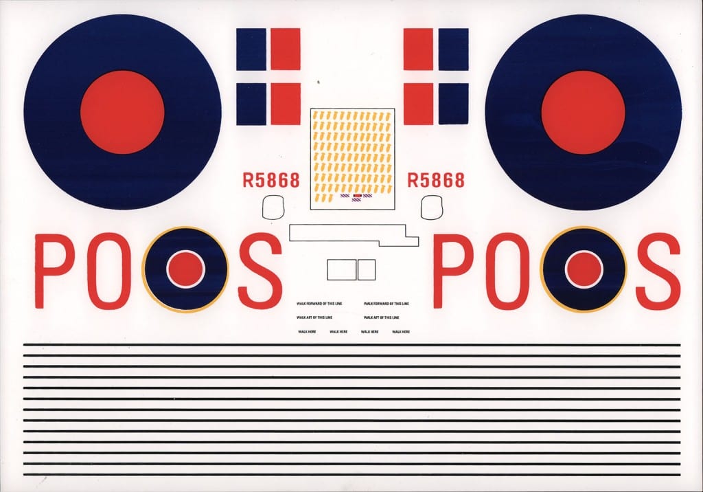
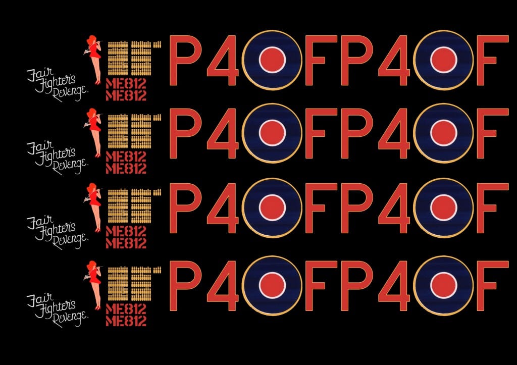
Before moving on to the decals which came in two groups; the decals which came with the model, and the decals which we had produced (with lots of spares).

Pic 24-23

Pic 24-24

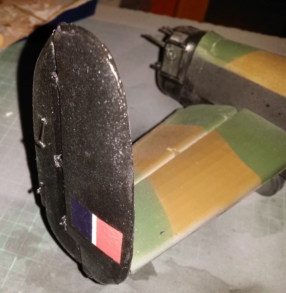
Once we’d added the flashes to the vertical stabilisers it became possible to permanently attach the horizontal and vertical stabilisers to the model and to add the two sets of weights to each of the rudders.

Pic 24-25

Pic 24-26

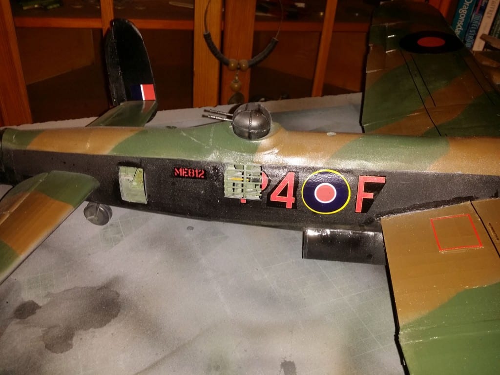
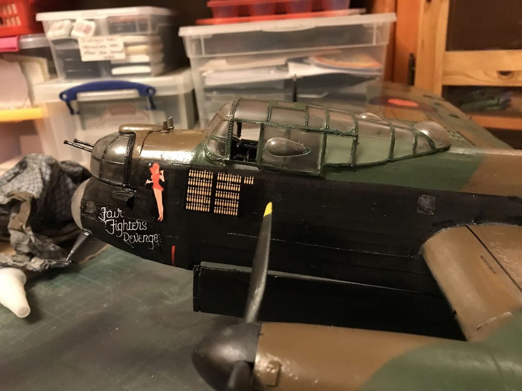
That done, we continued adding the decals to the relevant sections of the fuselage.

Pic 24-27 Pic 24-28 Pic 24-29 Pic 24-30 Pic 24-31 Pic 24-32

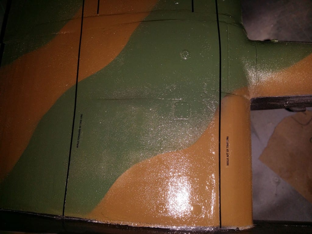
You will be able to see white lines and colour changes in the black surrounding the decals in the photographs above.  These were painted over to hide the edges of the decals, and a couple of layers of varnish were added to finish off the model.

Pic 24-33 Pic 24-34 Pic 24-35Pic 24-37

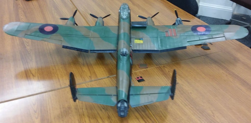
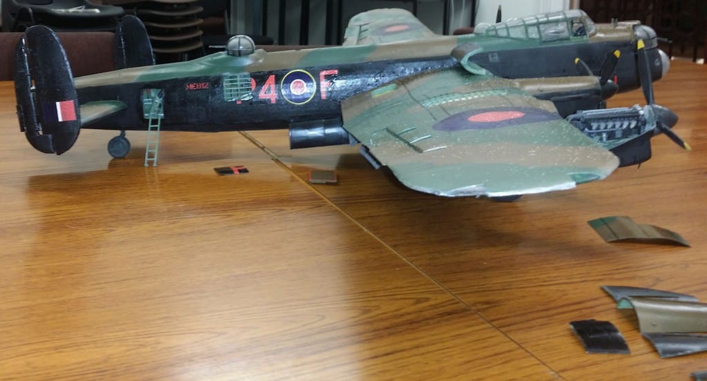
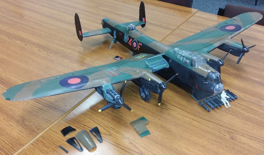
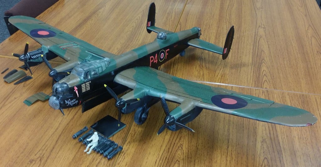
And, finally it was time to deliver the model the IBCC Digital Archive, where it will stay until we can find somewhere to keep it.

Pic 24-38 Pic 24-39 Pic 24-40 Pic 24-41 Pic 24-42

This is not the end of our work, we will be creating a diorama to place the model on over the next few weeks, and our progress will be covered on this blog, but the model aircraft itself is finished.

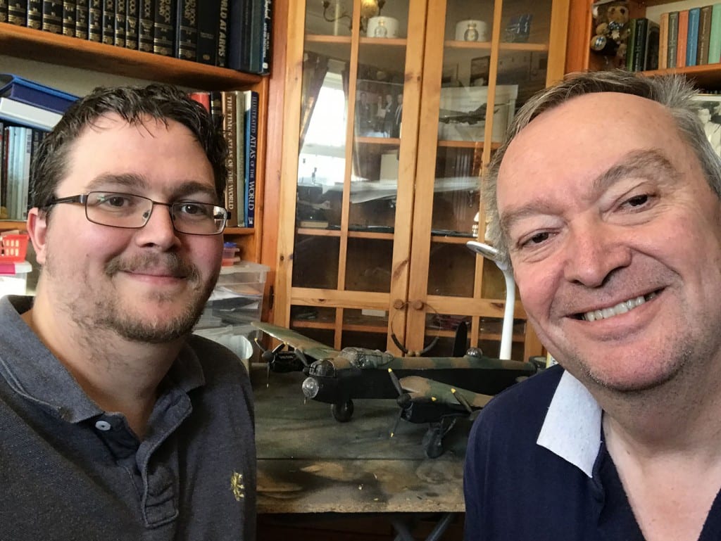
Here are two photographs of the main builders with the model, Robin Evans on the left, James Evans on the right.

Pic 24-43 Pic 24-44

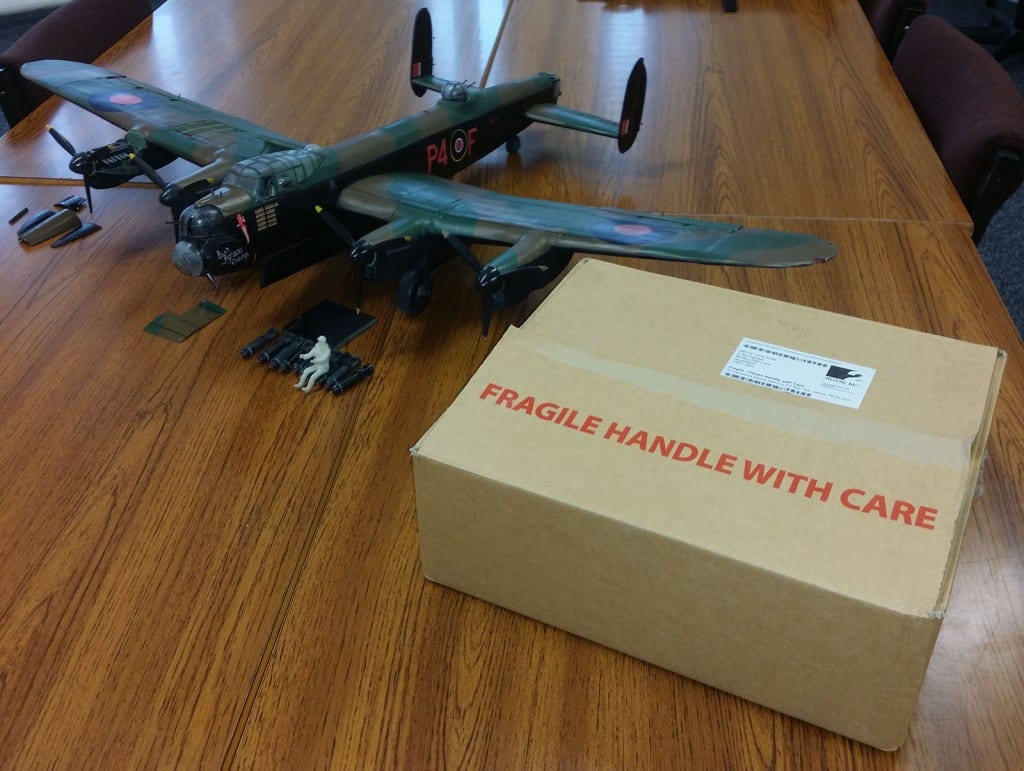
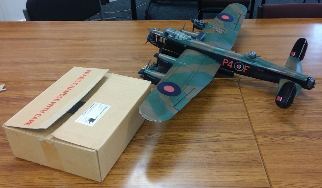
Finally, as a reminder of how far this build has come, the model with the box it came in.
Pic 24-45 Pic 24-46

Part 23 – The Results Are in…

Sorry to all for the long wait since the last build diary.  Things have been a little hectic lately for us and work on the model has slowed a little as a result.  That said, the results of our poll are in, as you may have seen almost 50% of respondents chose ME812 “Fair Fighter’s Revenge”.


Last time we spoke about the build specifically we had just finished the last big sections of the model, the bomb bay doors, and assembled the turrets.

Pic 22-24

Since then we’ve been working on evening out the fuselage by filling in any gaps.

Pic 23-01

And adding small details like hatch covers.

Pic 23-02

Before priming the whole surface to expose any flaws and repeating the whole process until satisfied.

Pic 23-03

Pic 23-04

Pic 23-05

Finally, we moved on to masking the model in preparation for the application of the first coat of paint.

Pic 23-06

Pic 23-07

Which was applied in black to the lower part of the model.

Pic 23-08

Pic 23-09

Pic 23-10

Recently though, we have been focussing on the process of creating decals for the model.

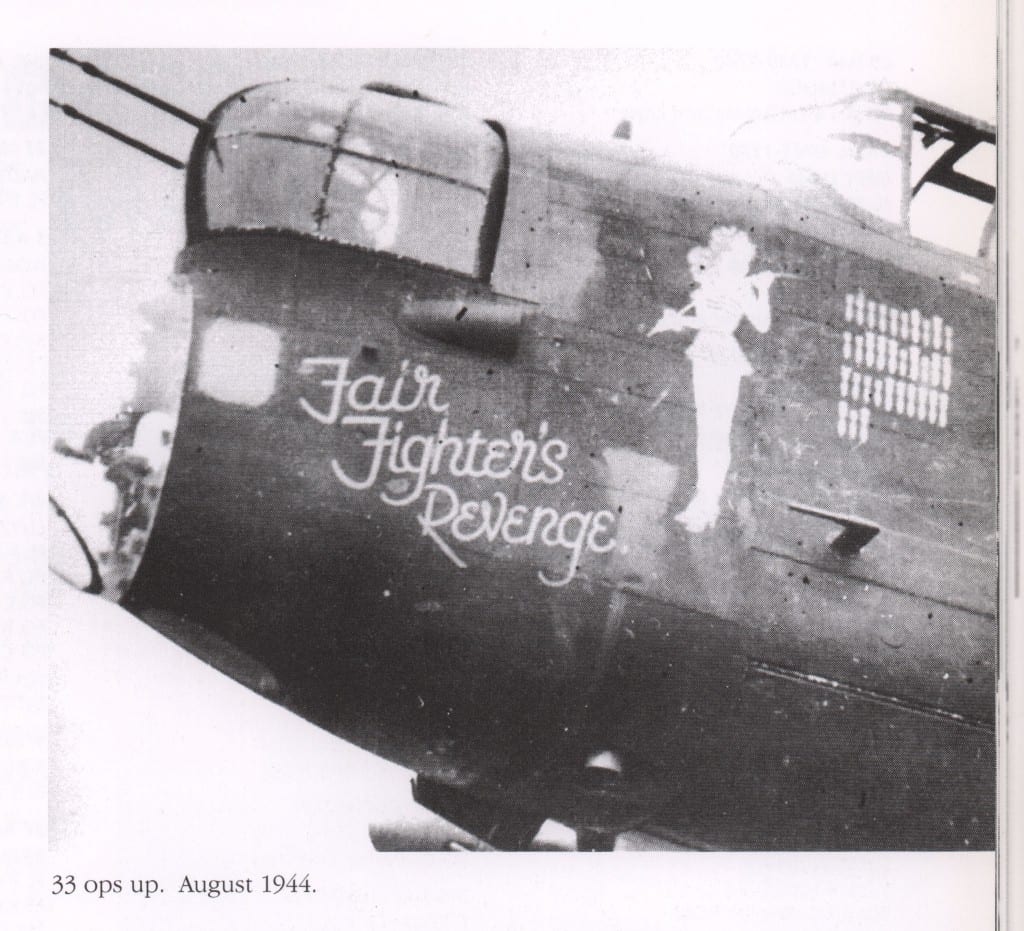
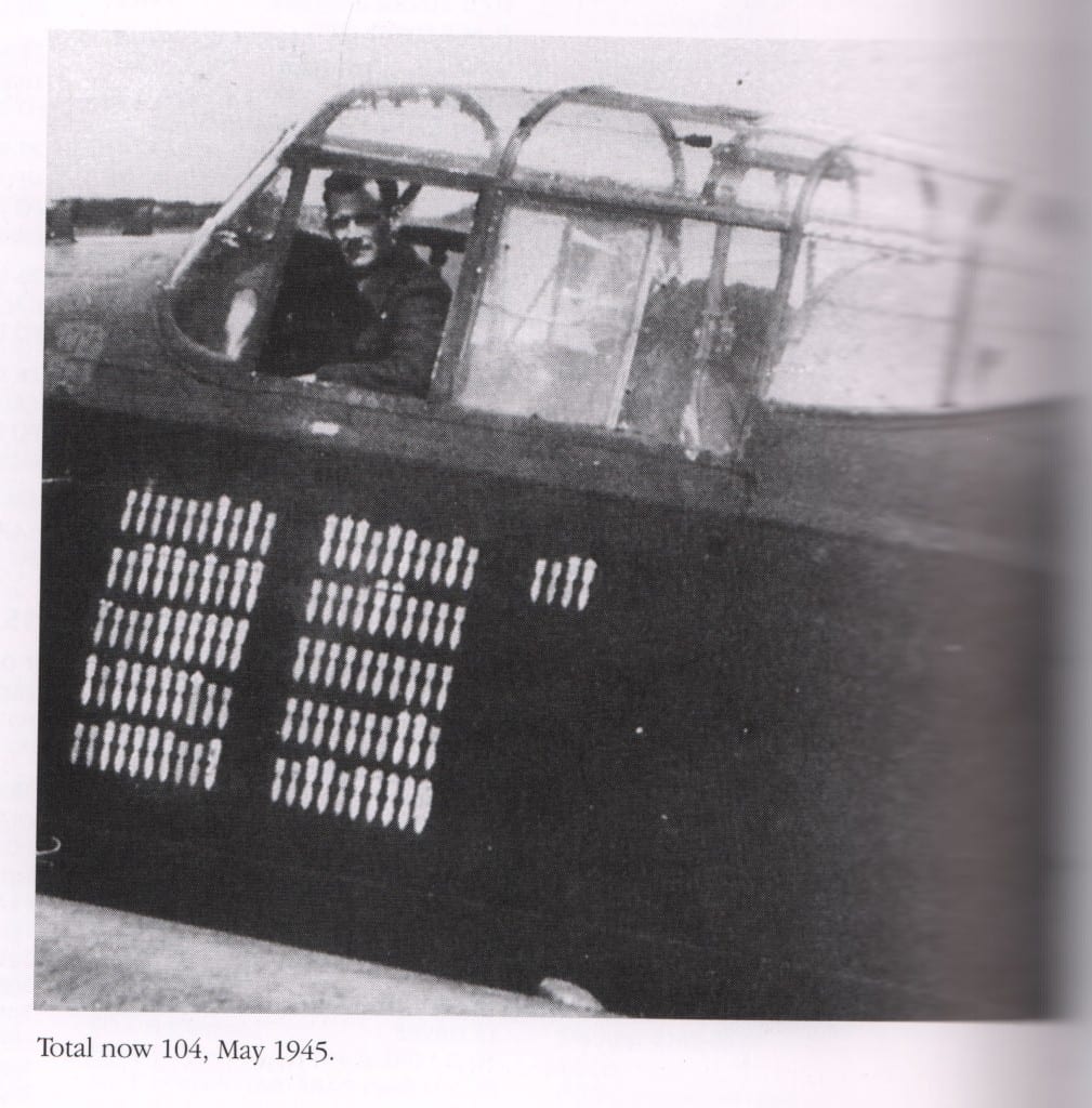
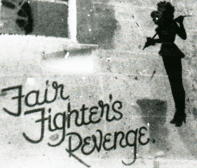
The first step, once the poll had closed was to obtain pictures of “Fair Fighter’s Revenge” which we could use to recreate the nose art and operation talley.  We found the most useful pictures in Norman Franks’ “Ton Up Lancs” from which the two photographs below were scanned (pages 169 and 170).

Pic 23-11

Pic 23-12

The first step was to take the first image and to manipulate it to remove perspective as much as possible.  We also ended up inverting the colours in order to maximise visibility.

Pic 23-13

Having done that, the process of recreating the text became one of tracing over the text with colour and then removing any excess, leaving this as a final result (also shown with a plain black background for clarity).

Pic 23-14

Pic 23-15

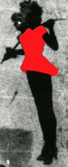
Next, came the far more complex task of recreating the nose art, a woman bearing a fencing foil (not a riding crop as I mistakenly stated in the poll entry). We decided to build up the image in a series of layers, the first of which was the dress.

Pic 23-16

Then the body, which, it must be said will be around an inch tall on the model (so please forgive the extremely poor quality of the art).

Pic 23-17

Then the hair, which was built up out of three separate layers to try and make it look slightly more like hair than it did originally.

Pic 23-18

The foil, which being an inanimate object was one of the more simple parts of the whole process.

Pic 23-19

And the subject’s shoes which underwent almost a dozen revisions on their own.

Pic 23-20

Finally, we were able to build up the entire image.

Pic 23-21

Pic 23-22

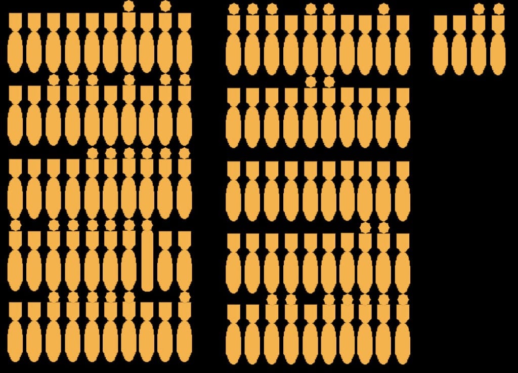
The next task was recreating the operation tally, which was made more complicated by the fact that no two squadrons seem to have used the same style for their tally marks.

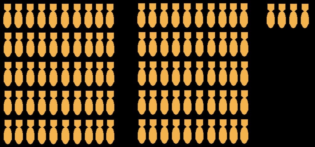
To make the operation tally we started by drawing a bomb (shown here with a black background for clarity).

Pic 23-23

Before copying the bomb nine times to create a line.

Pic 23-24

Then copying the line five times to create a block.

Pic 23-25

And then copying the block twice (before deleting the majority of the second copy) to create the full tally of 104 operations.

Pic 23-26

In addition to the bombs themselves, around 45 of the markers have an additional detail above the bomb, which it transpired was a sun or a star, which denoted that the operation had been flown in daylight (according to “Ton Up Lancs”).  We therefore created a sun symbol to be used.

Pic 23-27

Before copying it into all of the relevant positions.

Pic 23-28

We obtained the colour for the bombs (and the roundels for the next section) from the existing decals which came with the model (to finish it as S for Sugar R5868).

Pic 23-29

Next, we used a downloaded font to recreate the Squadron code and aircraft serial number.

Pic 23-30

Pic 23-31

We then assembled all of the components of the decals onto a single sheet.  Sizing them correctly in the process.

Pic 23-32

Before finally adding a few spares.

Pic 23-33

Bringing us to a close for this week.

Pic 23-34

For next time we hope to have the painting done and the decals affixed.

Part 22 – Trials and Errors

Hello again to all who are reading this.  As we approach the end of the build we’ve been thinking on all the suggestions that have been given to us over the last few weeks.  Later this week or early next week we will be putting up a poll of a short-list selected by the IBCC Digital Archive team from all the suggestions which were submitted to us for the decoration we should use.  At that point, the decision will be in your hands.

Last time we started on the nose and mid-upper turrets, finished off the rudders, the vertical stabilisers and added the skin panels to the nose section.

Pic 21-27

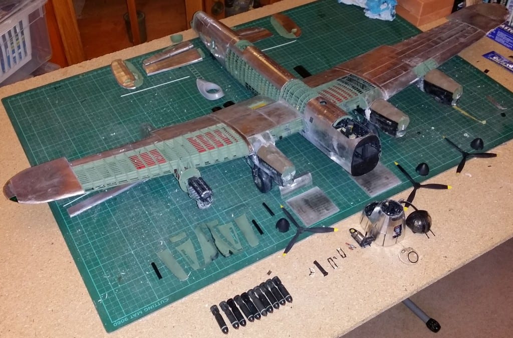
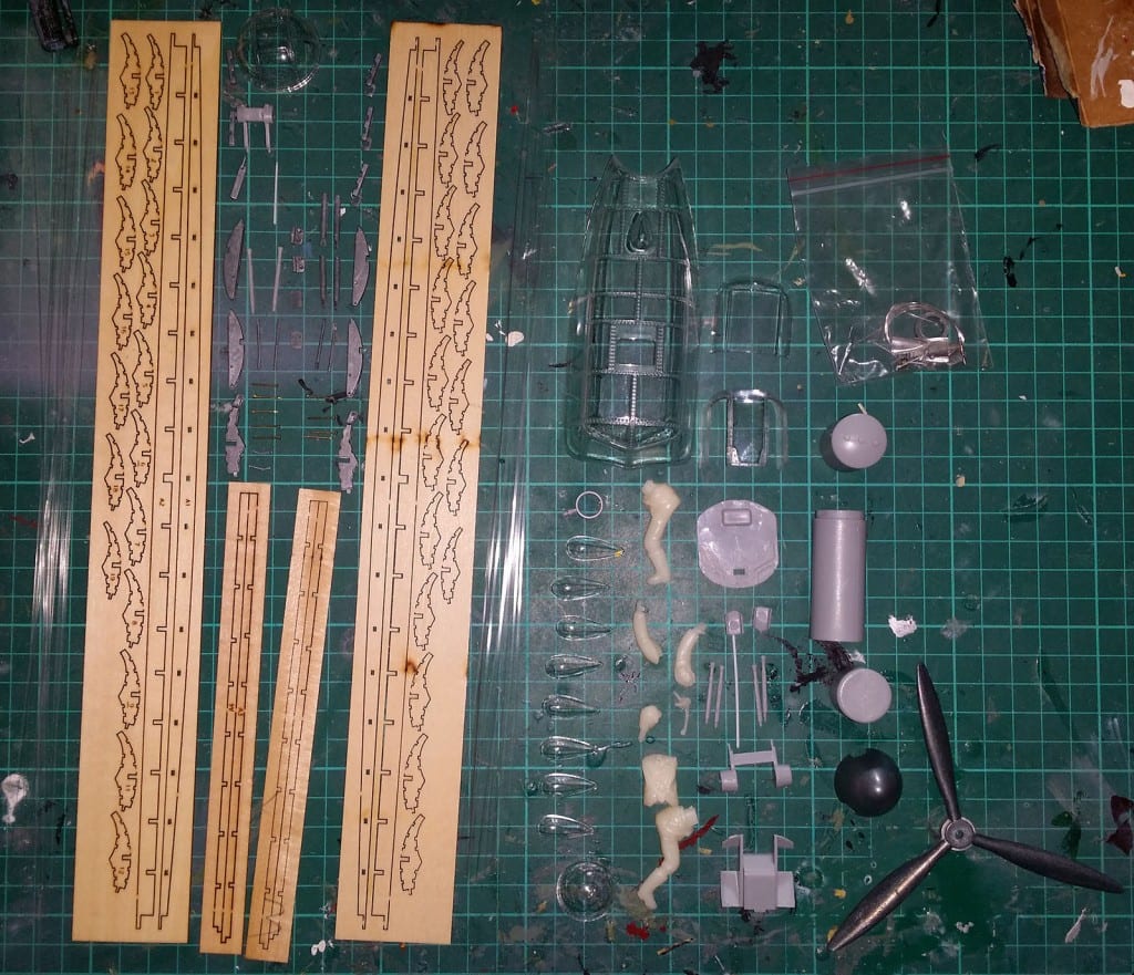
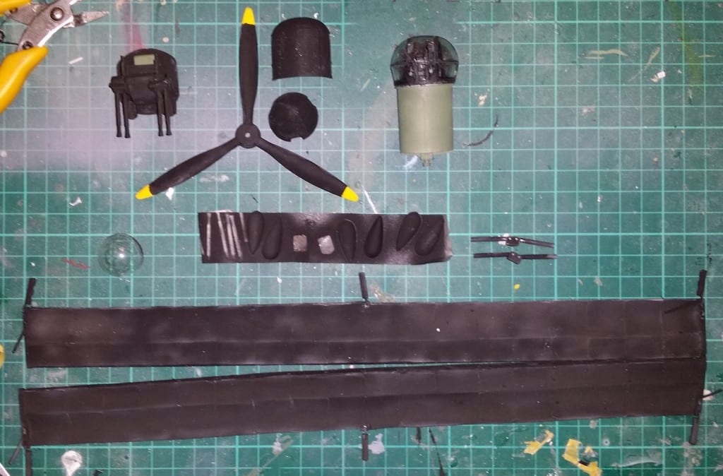
This time we worked on the mid-upper and rear turrets, the bomb-bay doors and started some work on the canopy.  Here are the parts which came with the relevant issues.

Pic 22-01

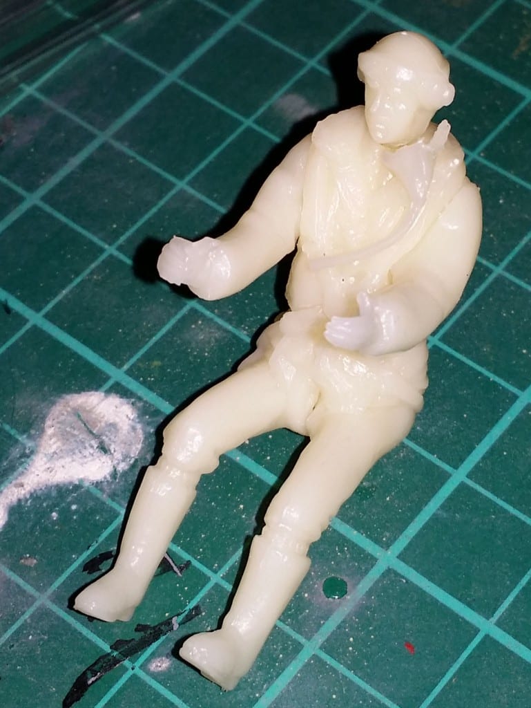
The first thing we did was to assemble the model of a pilot so that we could use it to properly position the foot pedals and control column in the cockpit.

Pic 22-02

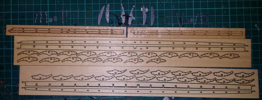
Next, we moved on to one of the major tasks of this diary entry, the construction of the two bomb-bay doors.

Starting with these parts.

Pic 22-03

First, we extracted all of the parts from their frames, and assembled the hinges.

Pic 22-05

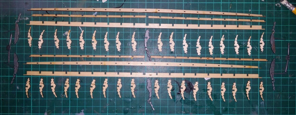
Then, we assembled the basic frame of the doors.

Pic 22-06

Before adding the stringers.

Pic 22-07

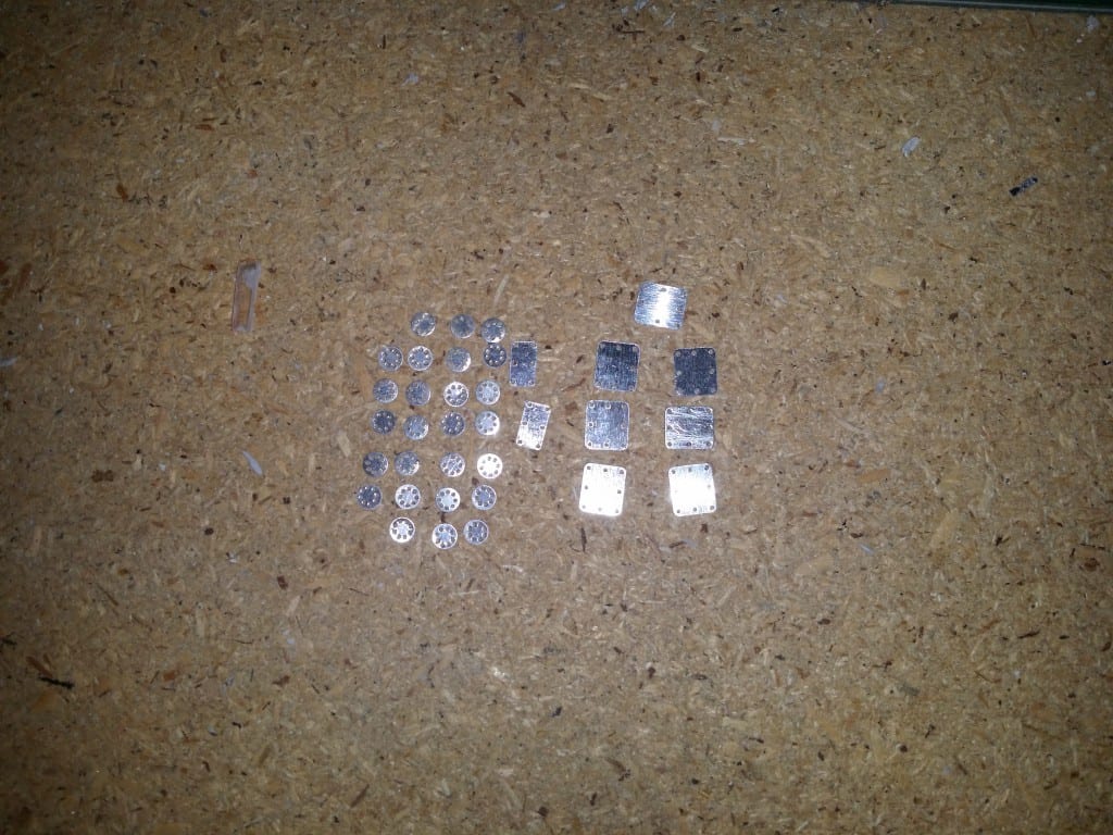
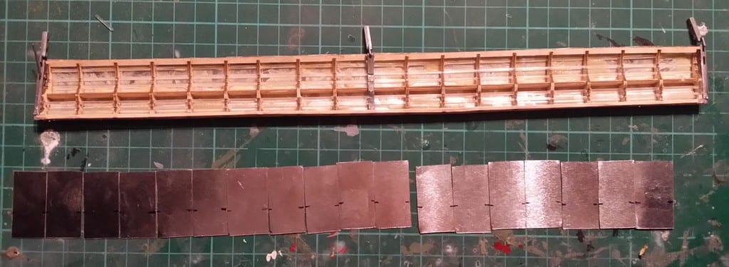
Having done this we then sanded the frame into shape, before beginning to prepare the 72 separate metal panels which were cut from a sheet of metal a few weeks ago (18 shown here).

Pic 22-08

Each of the panels had to be filed at the edges to ensure a smooth fit with their neighbours and had to be curved (by rolling the pieces over the handle of a knife) to fit the frame.

For the interior panels, even more work was needed.

The interior panels form two curves allowing large bombs (like the 4000lb HC bomb or “Cookie”) to fit inside the bomb-bay.

This meant that first, the line where the panel crossed the bar along the length of the doors had to be drawn onto the panels, followed by bending the panel at that point, and finally curving the two sides into shape.

Pic 22-09

Then, after all the panels had been glued on, we had to add filler to close any gaps, before sanding the doors down.

Pic 22-10

That done, the bomb-bay doors were set aside to be painted.

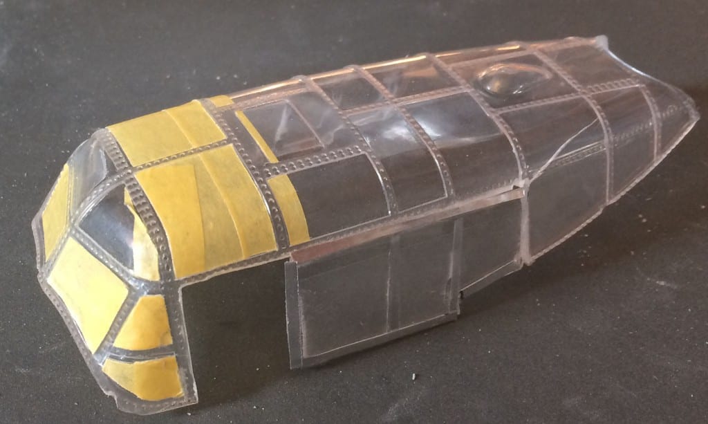
We next moved on to adding masking tape to the clear plastic pieces which make up the turrets and the astrodome.

First, we added masking tape, and then (with a very sharp knife) slowly cut away all the excess to leave these.

Pic 22-11

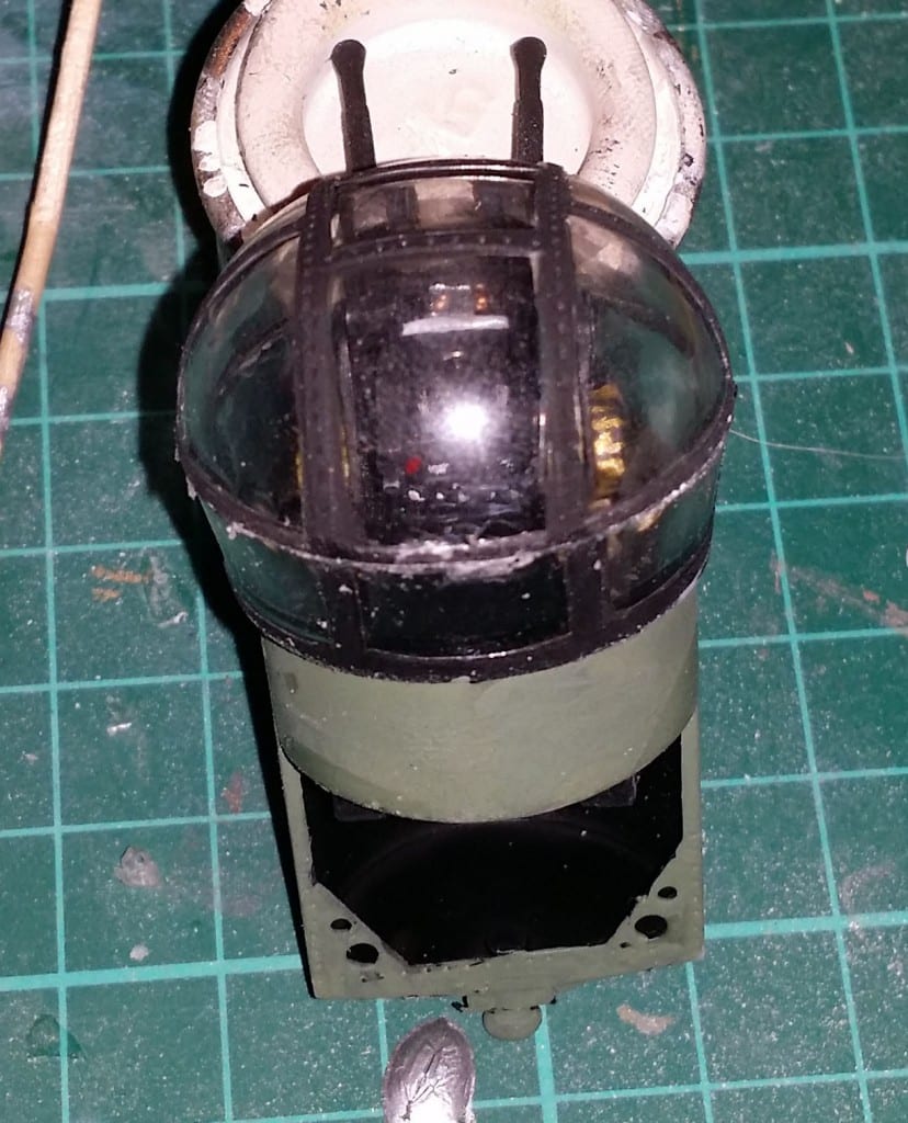
These were then set aside to be painted.  Unfortunately, whilst removing the masking tape from the rear turret following painting, I must have had either some superglue or some paint thinner on my hand.  The result was that the plastic turned foggy almost immediately, and we are currently working on how to salvage the rear turret.

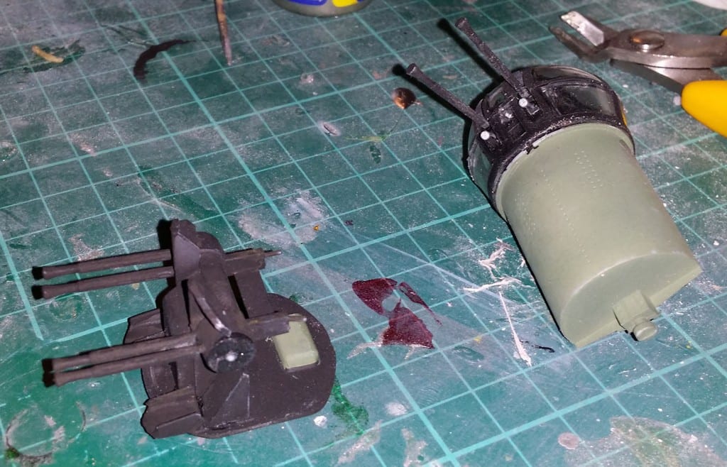
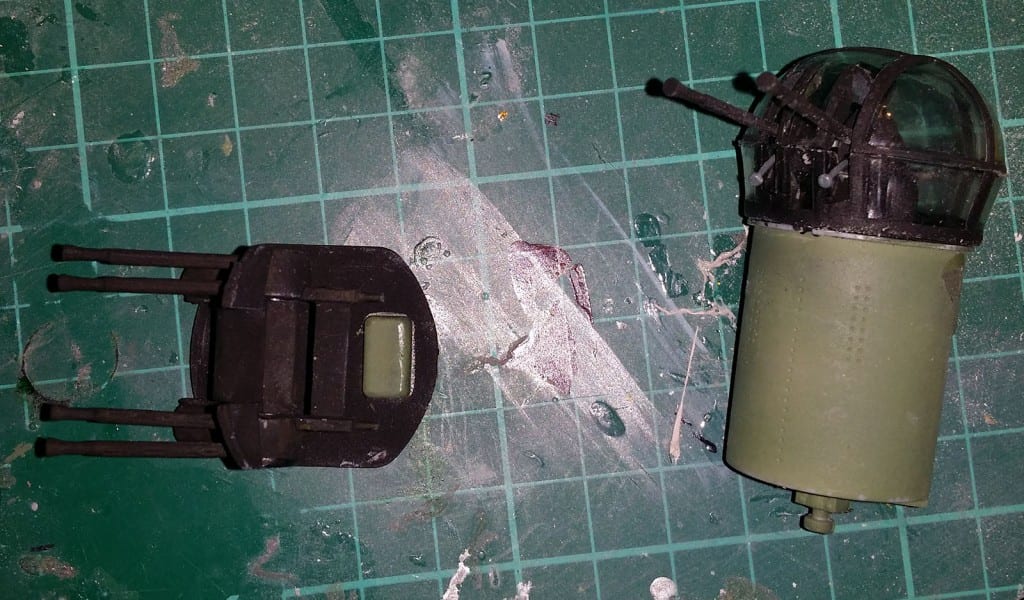
That having happened, we proceeded more carefully with assembling the mid-upper turret and the internal parts of the rear turret.

Pic 22-12 Pic 22-13 Pic 22-14

Below are all the parts worked on this week, including the last propeller and its spinner.

Pic 22-15

Whilst these were being worked on my father was assisting by attaching most of the remaining panels and using filler to close any gaps.  He was also attempting to solve the problem we encountered with the canopy (mentioned in last week’s interlude).

Int Pic 1 Int Pic 2 Pic 22-16 Pic 22-17 Pic 22-18

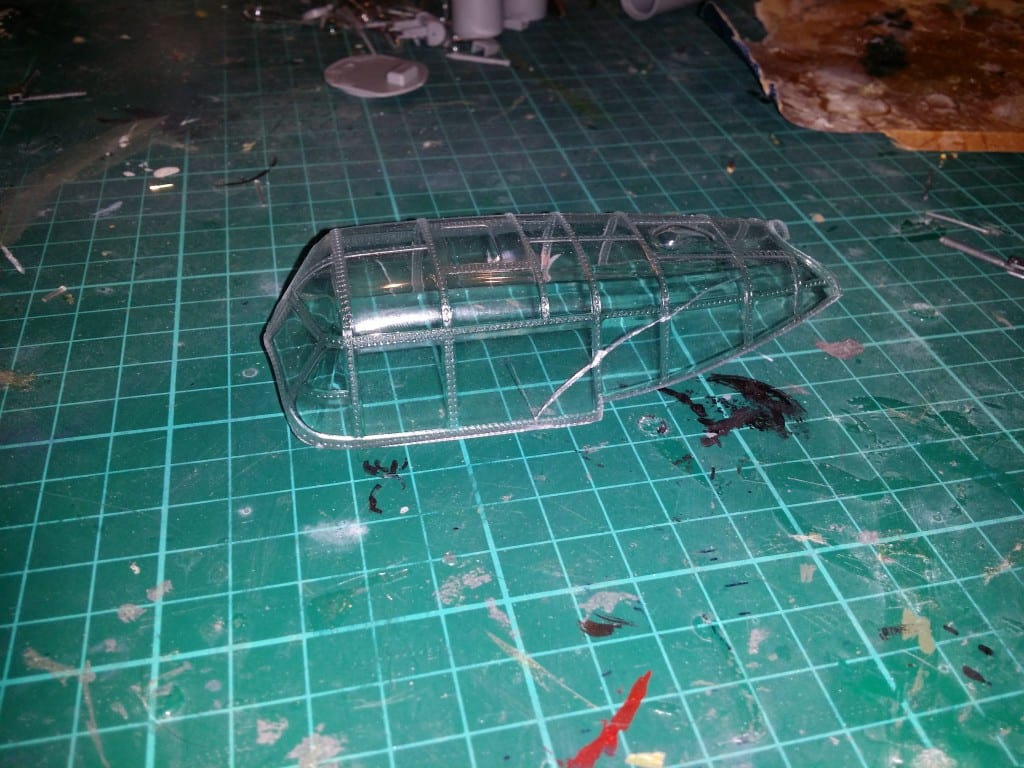
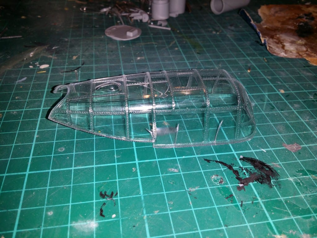
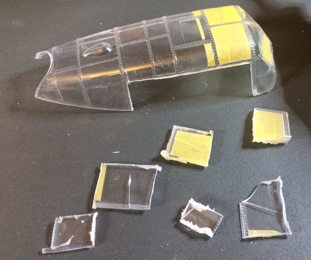
To that end, we decided that all the flat panels with cracks in should be removed and replaced with some plate styrene which we had available.  First, the damaged panels were removed.

Pic 22-19

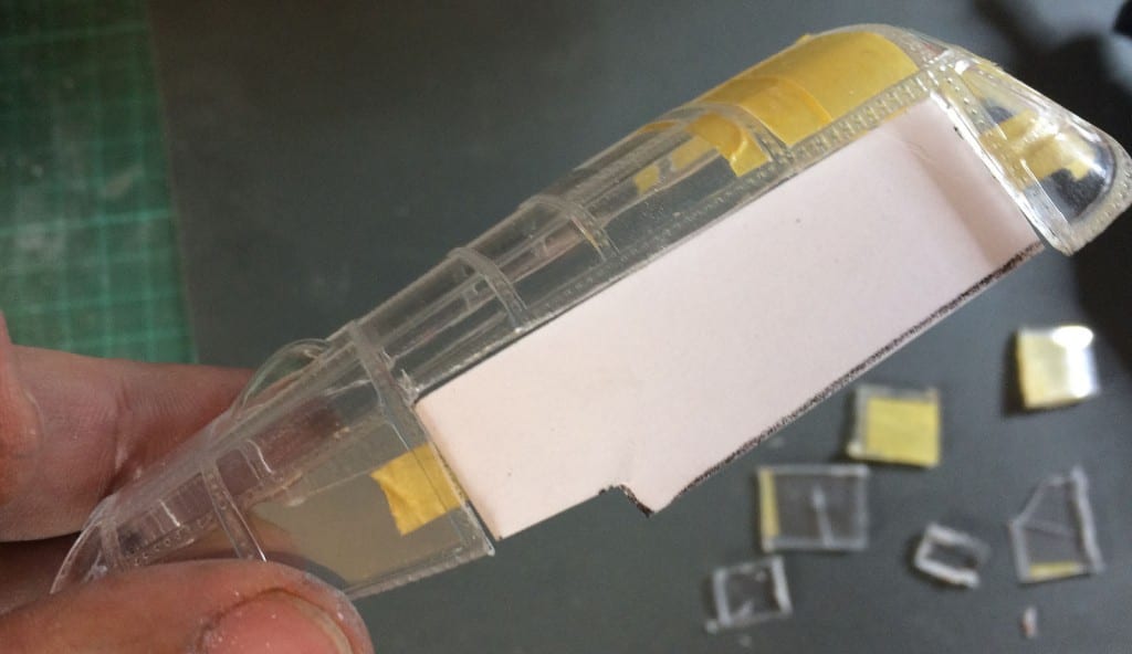
Then, a piece of card was used to obtain the shape and size of the panels.

Pic 22-20 Pic 22-21

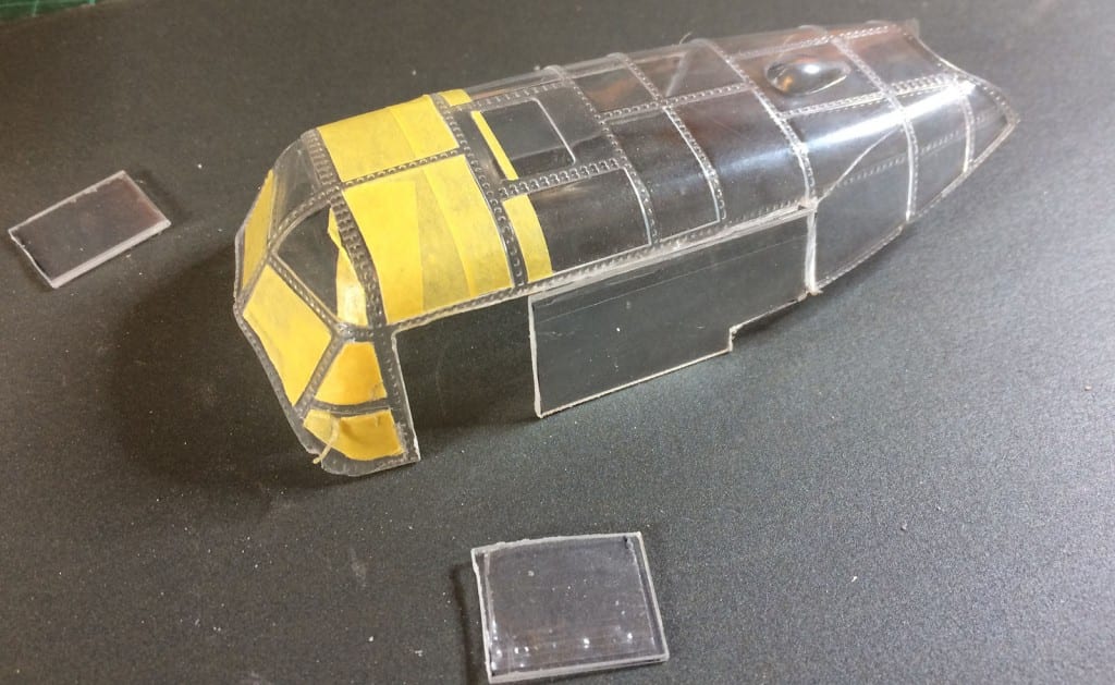
Finally, pieces of scrap metal were used to recreate the window frames.  The missing section is where the cockpit windows will be slid back, as they would be on the ground (we also intend to add a lower rail in that area).

Pic 22-22

Bringing us to our conclusion for this build diary.

Pic 22-23 Pic 22-24 Pic 22-25

Our hope is that the next build diary will be the last focussing on the Lancaster itself, and that the diary will cover attaching the last few details and painting the model.


Part 21 – Some Skin on my Nose

Welcome back to another build diary, thank you for your patience as we move into the final stages of this build.


This is your final chance to be heard in your opinion of which aircraft we should decorate this model as.  Last time we had a significant response extending our list from four potentials to nineteen.  Next time we’ll present everyone with our shortlist and ask you all to choose between them.  We would prefer if all of the suggestions had photographs of the aircraft, especially any nose art that we could use to guide us in our decorating.  The full list of potential aircraft is below:

  • An aircraft from 582 Squadron (Pathfinders) suggested by a member of Pathfinder Lodge 7255,
  • L7537 of 44 (Rhodesia) Squadron letters KM-L which was shot down on a mission to Dusseldorf in August 1942,
  • LL777 of 61 Squadron QR-S with its nose art of a hand holding a pair of playing cards,
  • LM360 of 61 Squadron QR-O the aircraft which Bill Reid won his Victoria Cross,
  • W4133 of 9 Squadron WS-Z “Zola” which we have good images for in the IBCC Digital Archive,
  • ? 61 Squadron QR-X,
  • JA914 57 Squadron DX-O lost over Berlin 3/4 September 1943,
  • LM621 100 Squadron HW-C lost on ops to Veirzon Rail Yards 1 July 1943,
  • ED497 ? Lost on Ops to Cologne,
  • LL687 408 Squadron HW-C “Berlin Special” suggestion provided with photograph,
  • 50 Squadron VN-B “Baker” flown in by Sir Michael Beetham and Reg Payne,
  • W4157 ? WS-V “Barbara Mary” Lost 17/18 January 1943 provided with photograph,
  • KB791 428 Squadron RCAF NA-A flown on by the proponent’s Grandfather,
  • ? 649 Squadron OJ-A “Heavenly Hilda”
  • ? 50 Squadron VN-N “Nan” an aircraft flown by James Flowers,
  • ? 619 Squadron PB-X Shot down over Heilbron 4 December 1944,
  • ME812 166 and 153 Squadrons AS-F/P4-F “Fair Fighter’s Revenge” flew 100+ operations including Ops Manna and Exodus,
  • JB405 12 Squadron “Hellzapoppin” Flown in by D Hayhurst, for whom we have a collection in the IBCC Digital Archive
  • “S-Sugar” the default which comes with the model.

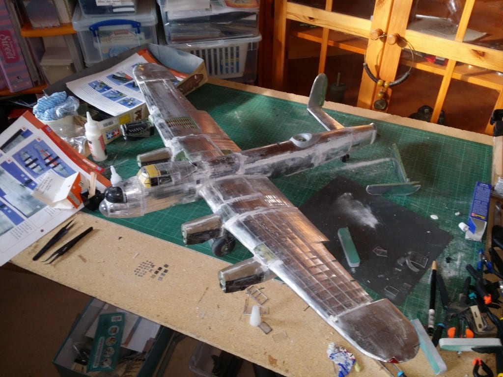
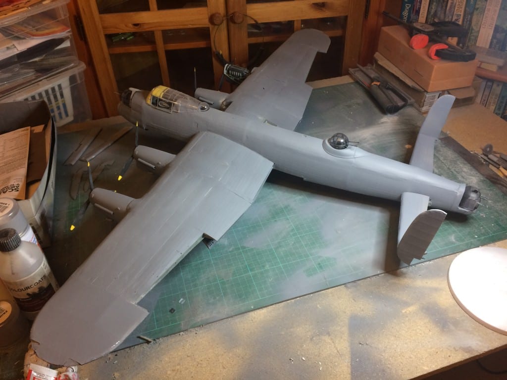
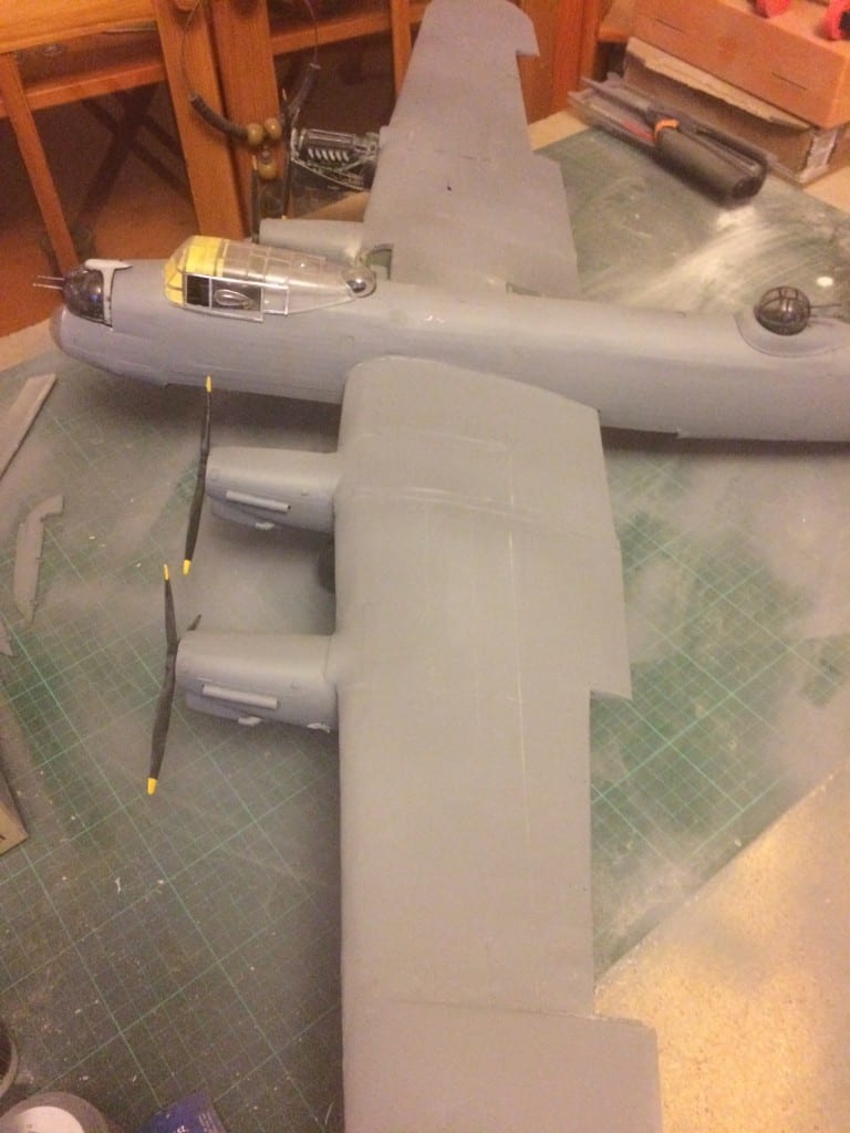
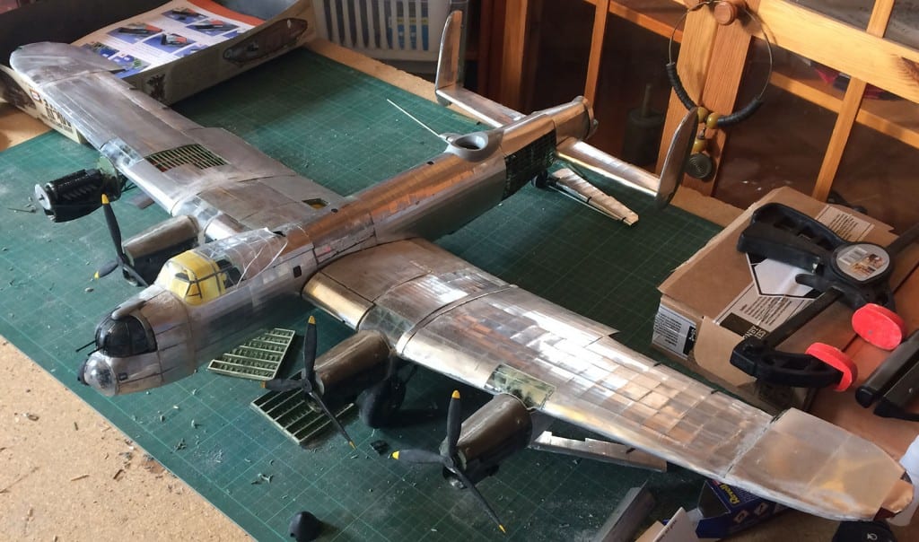
Moving on to the build diary, last time we attached the wings, and covered much of the fuselage in skin.

Pic 20-33

This time we started with these parts.

Pic 21-01

Plus all of the pieces we cut a few weeks ago for the bomb-aimer’s position.

First, we assembled the smaller pieces together to create some of the bomb-aimer’s control panels, hinges for the rudders, and the bomb-sight.

Pic 21-02

These were then set aside to be primed and painted.

Next, we masked up the nose turret canopy for painting, this took a lot of masking tape, a sharp knife and quite a bit of patience.  You can see it here next to some of the other components for the turret itself.

Pic 21-03

Having set aside those pieces for painting as well we moved on to marking up the pieces for rivet marking.  Here you can see all of the pieces of skin to cover the bomb-aimer’s position (18 separate pieces!) with the nose section.

Pic 21-04

And here are all of the pieces prepared for rivet marking, including the three panels which are designed to be detachable.

Pic 21-05

These than all had rivet markings applied, these are the last sections which need treating in this manner.

Pic 21-10

We then attached the hinges to the rudders.  You may notice that one of the hinges is missing.  One of the “T” plates was missing when we opened the bag, the other half of the hinge was applied in the correct place on the main model.

Pic 21-11

Before we finally moved on to painting everything.

Pic 21-12

The nose turret and bomb-aimer’s blister went together pretty quickly after that, as did the installation of the newly finished control panels and the bomb-sight.

Pic 21-13

Here’s a slightly closer view of the nose turret fully completed.

Pic 21-14

The Bomb-sight and control panels, and the cupola.

Pic 21-16

Pic 21-15

And the bomb aimer’s bench.

Pic 21-17

Before we moved on to attaching all of the fuselage panels.

Pic 21-18

And here is a view back through the bomb-aimer’s position from where the cockpit will be.

Pic 21-23

Finally, the blister’s support ring was added along with the two “A-frames” which go inside the blister.

Pic 21-25

Next, the skin and rudders where attached to the vertical stabilisers.  Then these parts were set aside to be painted with the rest of the aircraft.

Pic 21-24

Whilst all of this was going on I had passed the task of getting the engine, undercarriage bay and nacelle cowlings to actually fit together to a modeller with far more experience than I.

After a few attempts he determined that the sections of the under carriage cowlings that were meant to follow the engine bulkhead would never be able to maintain the proper shape, so he removed them and replaced them with a strip of scrap metal from the process of cutting fuselage panels.

Pic 21-06

Before using filler to close gaps around the edges.

Pic 21-07 Pic 21-08 Pic 21-09

He later removed much of the filler, but has not yet reached as far as the dorsal side of the model.

That brings us to the end of this build diary.

Pic 21-26

Pic 21-27

Pic 21-28

Next time we will be building the two bomb-bay doors (with their 72 skin panels), finishing the fuselage and building the other two turrets.

Part 20 – So much to do, so little time

Sorry to all again for missing last week’s planned update, unfortunately as we approach the end of the build process the complexity of the work is increasing.  As such, for the last three Build Diaries (covering issues 117-120, 121-124 and 125) we will only produce them when they are actually ready.


We are still open to suggestions for aircraft to build the model as, the ones which have been suggested thus far are as follows:

An aircraft from 582 Squadron (Pathfinders) suggested by a member of Pathfinder Lodge 7255,

L7537 of 44 (Rhodesia) Squadron letters KM-L which was shot down on a mission to Dusseldorf in August 1942,

LL777 of 61 Squadron QR-S with its nose art of a hand holding a pair of playing cards,

S for Sugar (the default which comes with the kit).


Any others would be gratefully appreciated, especially if there is a photograph or art showing any nose art.


That said, I can now finally show you our work for the last fortnight.

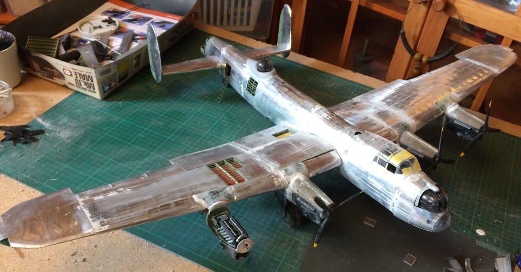
Last time the main focus of attention was the cutting out of the various fuselage panels and the assembly of the model minus the bomb-aimer’s position and the wings.

Pic 19-42

This time we’ll be working on attaching the wings, adding in some of the bomb-aimer’s equipment, and covering most of the fuselage with metal skin.

The parts for this diary were as shown here.

Pic 20-01

With the skin sheets (all marked up for adding rivet marks) shown here.

Pic 20-02

And with the proper rivet marks and curvature (achieved by bending the sheets around a knife handle and checking frequently against the curvature of the frame).

Pic 20-03

After marking out the rivet lines the next step was to build one of the control panels from the bomb-aimer’s position, and the escape hatch for the same.

First was removing the parts from their frets.

Pic 20-04

And then gluing the parts into their final format.

Pic 20-05

Before adding the small metal detailing parts, also shown here is the guard rail which had its middle rail attached at this stage.

Pic 20-06

Then the two metal skin pieces for the escape hatch were attached to the frame and filed into shape.

Pic 20-07

All of these parts were then set aside to be painted.

Before moving on to that task, six small detail parts (part of the aileron attachments) were laid out (three are shown here).

Pic 20-08

And holes were drilled into the upper skin of the two wings to hold them before they were glued in.
Pic 20-09

This photograph shows the plastic mouldings which will cover the engines and undercarriage bays following preparation for painting.

Pic 20-10

These were also set aside to be painted.

As shown in these photographs.

Pic 20-14

Pic 20-15

Pic 20-16

Pic 20-11

The set of pieces in the second photograph were then taken to form the joint in the two wings.

Pic 20-12

Before the two wings were attached to the fuselage for the first time.

Pic 20-13

Unfortunately, as discussed in last week’s interlude, things didn’t go according to plan and the work had to be redone.

Pic 20-17

Pic 20-18

The joint was then strengthened with stringers crossing from one frame to another.  Then a strip of metal skin was placed over the joint.

Next, the radiators were added to the engines and the loose wires attached to them.

Pic 20-19

With the painting done, attention could turn back to finishing off the bomb-aimer’s control panel and the camera.

Pic 20-20

Before installing two metal panels into the interior of the bomb-aimer’s position.
Pic 20-21

And then adding the control panel, camera and safety rail.

Pic 20-22

Pic 20-23

Pic 20-24

This section was then set aside until the next Build Diary.
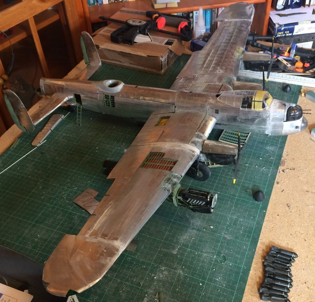
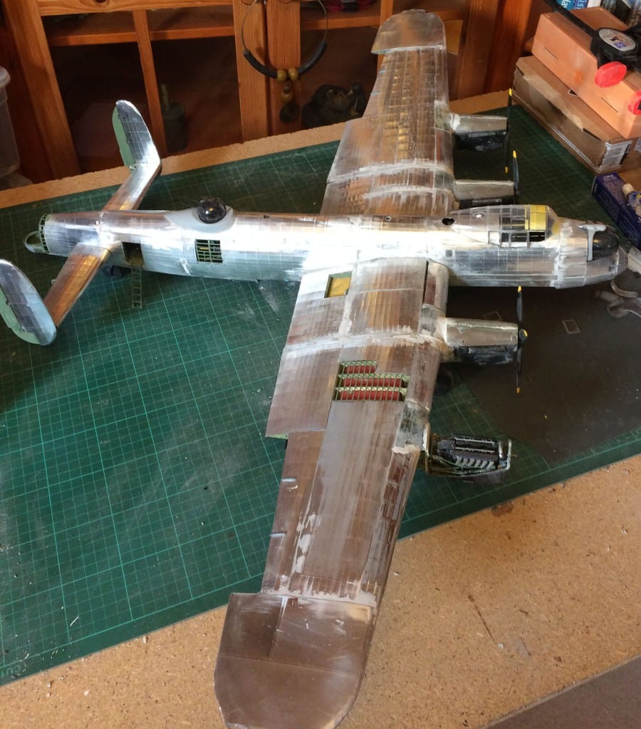
The last task for this build diary was to take the skin sections prepared a fortnight ago, and add them to the frame.

Pic 20-25

Pic 20-26

Pic 20-27

Including adding both skin and navigation lights to the two wing-tips.

Pic 20-28

Pic 20-29

And the horizontal stabilisers.

Pic 20-30

Bringing us to the end of this build diary.

Pic 20-31

Pic 20-32

Pic 20-33